Brother International MFC 8500 Service Manual - Page 117
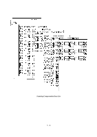
Printout of Scanning Compensation Data, A/D-low value 1 byte
 |
UPC - 012502603832
View all Brother International MFC 8500 manuals
Add to My Manuals
Save this manual to your list of manuals |
Page 117 highlights
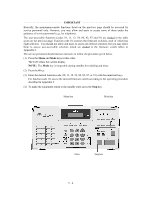
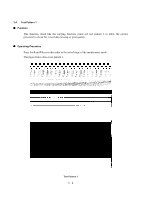
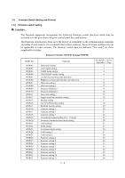
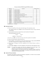
3.2 Printout of Scanning Compensation Data n Function The equipment prints out the white and black level data for scanning compensation. n Operating Procedure Do not start this function merely after powering on the equipment but start it after carrying out a sequence of scanning operation. Unless the equipment has carried out any scanning operation, this function cannot print out correct scanning compensation data. This is because at the start of scanning operation, the equipment initializes white and black level data and takes in the scanning compensation reference data. (1) Press the 0 and 5 keys in this order in the initial stage of the maintenance mode. The "WHITE LEVEL 1" will appear on the LCD. (2) The equipment prints out the scanning compensation data list containing the following: a) LED light intensity value (1 byte) b) A/D-high value (1 byte) c) A/D-low value (1 byte) d) Compensation data for background color (1 byte) e) 2-value quantization black level data (2464 bytes) f) 2-value quantization white level data (2464 bytes) (3) Upon completion of recording of the compensation data list, the equipment returns to the initial stage of the maintenance mode. NOTE: If any data is abnormal, its code will be printed in inline style, as shown on the next page. V - 5
-
 1
1 -
2
-
3
-
4
-
5
-
6
-
7
-
8
-
9
-
10
-
11
-
12
-
13
-
14
-
15
-
16
-
17
-
18
-
19
-
20
-
21
-
22
-
23
-
24
-
25
-
26
-
27
-
28
-
29
-
30
-
31
-
32
-
33
-
34
-
35
-
36
-
37
-
38
-
39
-
40
-
41
-
42
-
43
-
44
-
45
-
46
-
47
-
48
-
49
-
50
-
51
-
52
-
53
-
54
-
55
-
56
-
57
-
58
-
59
-
60
-
61
-
62
-
63
-
64
-
65
-
66
-
67
-
68
-
69
-
70
-
71
-
72
-
73
-
74
-
75
-
76
-
77
-
78
-
79
-
80
-
81
-
82
-
83
-
84
-
85
-
86
-
87
-
88
-
89
-
90
-
91
-
92
-
93
-
94
-
95
-
96
-
97
-
98
-
99
-
100
-
101
-
102
-
103
-
104
-
105
-
106
-
107
-
108
-
109
-
110
-
111
-
 112
112 -
 113
113 -
 114
114 -
 115
115 -
 116
116 -
 117
117 -
 118
118 -
 119
119 -
 120
120 -
 121
121 -
 122
122 -
123
-
124
-
125
-
126
-
127
-
128
-
129
-
130
-
131
-
132
-
133
-
134
-
135
-
136
-
137
-
138
-
139
-
140
-
141
-
142
-
143
-
144
-
145
-
146
-
147
-
148
-
149
-
150
-
151
-
152
-
153
-
154
-
155
-
156
-
157
-
158
-
159
-
160
-
161
-
162
-
163
-
164
-
165
-
166
-
167
-
168
-
169
-
170
-
171
-
172
-
173
-
174
-
175
-
176
-
177
-
178
-
179
-
180
-
181
-
182
-
183
-
184
-
185
-
186
-
187
-
188
-
189
-
190
-
191
-
192
-
193
-
194
-
195
-
196
-
197
-
198
-
199
-
200
-
201
-
202
-
203
-
204
-
205
-
206
-
207
-
208
-
209
-
210
-
211
-
212
-
213
-
214
-
215
-
216
-
217
-
218
-
219
-
220
-
221
-
222
-
223
-
224
-
225
-
226
-
227
-
228
-
229
-
230
-
231
-
232
-
233
-
234
-
235
-
236
-
237
-
238
-
239
 |
 |