Brother International MFC 8500 Service Manual - Page 91
Bottom Plate, Main PCB, and Bottom Insulation Film
 |
UPC - 012502603832
View all Brother International MFC 8500 manuals
Add to My Manuals
Save this manual to your list of manuals |
Page 91 highlights
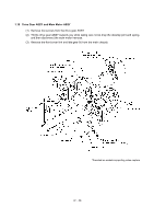
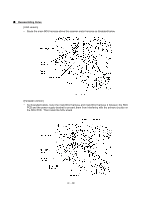
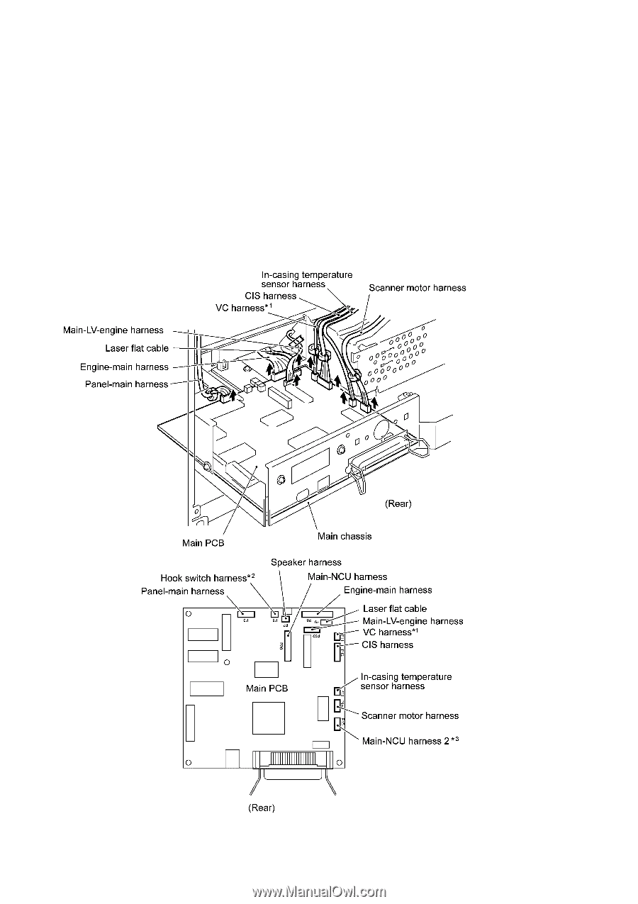
1.21 Bottom Plate, Main PCB, and Bottom Insulation Film (1) Disconnect the following harnesses and flat cable from the main PCB: • Panel-main harness (6-pin, P3) • Main-LV-engine harness (6-pin, P22) • Laser flat cable (P9) • Engine-main harness (12-pin, P8) • VC harness*1 (2-pin, P11) • CIS harness (7-pin, P12) • In-casing temperature sensor harness (2-pin, P13) • Scanner motor harness (4-pin, P14) *1 Provided on models supporting video capture *2 Provided on models equipped with a handset *3 Provided on the European version IV - 50
-
 1
1 -
2
-
3
-
4
-
5
-
6
-
7
-
8
-
9
-
10
-
11
-
12
-
13
-
14
-
15
-
16
-
17
-
18
-
19
-
20
-
21
-
22
-
23
-
24
-
25
-
26
-
27
-
28
-
29
-
30
-
31
-
32
-
33
-
34
-
35
-
36
-
37
-
38
-
39
-
40
-
41
-
42
-
43
-
44
-
45
-
46
-
47
-
48
-
49
-
50
-
51
-
52
-
53
-
54
-
55
-
56
-
57
-
58
-
59
-
60
-
61
-
62
-
63
-
64
-
65
-
66
-
67
-
68
-
69
-
70
-
71
-
72
-
73
-
74
-
75
-
76
-
77
-
78
-
79
-
80
-
81
-
82
-
83
-
84
-
85
-
 86
86 -
 87
87 -
 88
88 -
 89
89 -
 90
90 -
 91
91 -
 92
92 -
 93
93 -
 94
94 -
 95
95 -
 96
96 -
97
-
98
-
99
-
100
-
101
-
102
-
103
-
104
-
105
-
106
-
107
-
108
-
109
-
110
-
111
-
112
-
113
-
114
-
115
-
116
-
117
-
118
-
119
-
120
-
121
-
122
-
123
-
124
-
125
-
126
-
127
-
128
-
129
-
130
-
131
-
132
-
133
-
134
-
135
-
136
-
137
-
138
-
139
-
140
-
141
-
142
-
143
-
144
-
145
-
146
-
147
-
148
-
149
-
150
-
151
-
152
-
153
-
154
-
155
-
156
-
157
-
158
-
159
-
160
-
161
-
162
-
163
-
164
-
165
-
166
-
167
-
168
-
169
-
170
-
171
-
172
-
173
-
174
-
175
-
176
-
177
-
178
-
179
-
180
-
181
-
182
-
183
-
184
-
185
-
186
-
187
-
188
-
189
-
190
-
191
-
192
-
193
-
194
-
195
-
196
-
197
-
198
-
199
-
200
-
201
-
202
-
203
-
204
-
205
-
206
-
207
-
208
-
209
-
210
-
211
-
212
-
213
-
214
-
215
-
216
-
217
-
218
-
219
-
220
-
221
-
222
-
223
-
224
-
225
-
226
-
227
-
228
-
229
-
230
-
231
-
232
-
233
-
234
-
235
-
236
-
237
-
238
-
239
 |
 |
IV
- 50
1.21
Bottom Plate, Main PCB, and Bottom Insulation Film
(1)
Disconnect the following harnesses and flat cable from the main PCB:
• Panel-main harness (6-pin, P3)
• Main-LV-engine harness (6-pin, P22)
• Laser flat cable (P9)
• Engine-main harness (12-pin, P8)
• VC harness*
1
(2-pin, P11)
• CIS harness (7-pin, P12)
• In-casing temperature sensor harness (2-pin, P13)
• Scanner motor harness (4-pin, P14)
*
1
Provided on models supporting video capture
*
2
Provided on models equipped with a handset
*
3
Provided on the European version