Brother International MFC 8500 Service Manual - Page 129
CIS Scanner Area Setting, 3.12 EEPROM Customizing, Function, Operating Procedure
 |
UPC - 012502603832
View all Brother International MFC 8500 manuals
Add to My Manuals
Save this manual to your list of manuals |
Page 129 highlights
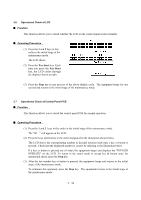
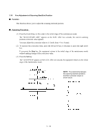
3.11 CIS Scanner Area Setting n Function The equipment sets the CIS scanner area and stores it into the EEPROM. n Operating Procedure (1) Press the 5 key twice in the initial stage of the maintenance mode. The "SCANNER AREA SET" will appear on the LCD. The equipment checks and sets the area to be scanned. If no error is noted, the equipment returns to the initial stage of the maintenance mode. If any error is noted, the "SCANNER ERROR" will appear on the LCD. To return the equipment to the initial stage of the maintenance mode, press the Stop key. 3.12 EEPROM Customizing n Function This function allows you to customize the EEPROM according to language, function settings, and firmware switch settings. The customizing codes list is given in Appendix 1. NOTE: If you replace the main PCB, be sure to carry out this procedure. n Operating Procedure (1) Press the 7 and 4 keys in this order in the initial stage of the maintenance mode. The current customizing code (e.g., 9001 in the case of MFC8500 USA version) appears. (2) Enter the desired customizing code (e.g., 0002 in the case of MFC8500 Canadian version). The newly entered code appears. NOTE: If a wrong 4-digit code is entered, the equipment will malfunction. (3) Press the Fax Start key. The equipment saves the setting and returns to the initial stage of the maintenance mode. If you press the Stop key or no keys are pressed for one minute in the above procedure, the equipment stops the procedure and returns to the initial stage of the maintenance mode. V - 17
-
 1
1 -
2
-
3
-
4
-
5
-
6
-
7
-
8
-
9
-
10
-
11
-
12
-
13
-
14
-
15
-
16
-
17
-
18
-
19
-
20
-
21
-
22
-
23
-
24
-
25
-
26
-
27
-
28
-
29
-
30
-
31
-
32
-
33
-
34
-
35
-
36
-
37
-
38
-
39
-
40
-
41
-
42
-
43
-
44
-
45
-
46
-
47
-
48
-
49
-
50
-
51
-
52
-
53
-
54
-
55
-
56
-
57
-
58
-
59
-
60
-
61
-
62
-
63
-
64
-
65
-
66
-
67
-
68
-
69
-
70
-
71
-
72
-
73
-
74
-
75
-
76
-
77
-
78
-
79
-
80
-
81
-
82
-
83
-
84
-
85
-
86
-
87
-
88
-
89
-
90
-
91
-
92
-
93
-
94
-
95
-
96
-
97
-
98
-
99
-
100
-
101
-
102
-
103
-
104
-
105
-
106
-
107
-
108
-
109
-
110
-
111
-
112
-
113
-
114
-
115
-
116
-
117
-
118
-
119
-
120
-
121
-
122
-
123
-
 124
124 -
 125
125 -
 126
126 -
 127
127 -
 128
128 -
 129
129 -
 130
130 -
 131
131 -
 132
132 -
 133
133 -
 134
134 -
135
-
136
-
137
-
138
-
139
-
140
-
141
-
142
-
143
-
144
-
145
-
146
-
147
-
148
-
149
-
150
-
151
-
152
-
153
-
154
-
155
-
156
-
157
-
158
-
159
-
160
-
161
-
162
-
163
-
164
-
165
-
166
-
167
-
168
-
169
-
170
-
171
-
172
-
173
-
174
-
175
-
176
-
177
-
178
-
179
-
180
-
181
-
182
-
183
-
184
-
185
-
186
-
187
-
188
-
189
-
190
-
191
-
192
-
193
-
194
-
195
-
196
-
197
-
198
-
199
-
200
-
201
-
202
-
203
-
204
-
205
-
206
-
207
-
208
-
209
-
210
-
211
-
212
-
213
-
214
-
215
-
216
-
217
-
218
-
219
-
220
-
221
-
222
-
223
-
224
-
225
-
226
-
227
-
228
-
229
-
230
-
231
-
232
-
233
-
234
-
235
-
236
-
237
-
238
-
239
 |
 |