Brother International MFC 8500 Service Manual - Page 68
Main Cover, provided in the main cover is dislocated from the power inlet.
 |
UPC - 012502603832
View all Brother International MFC 8500 manuals
Add to My Manuals
Save this manual to your list of manuals |
Page 68 highlights
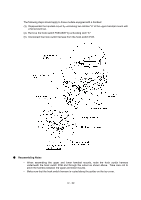
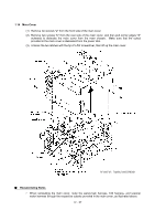
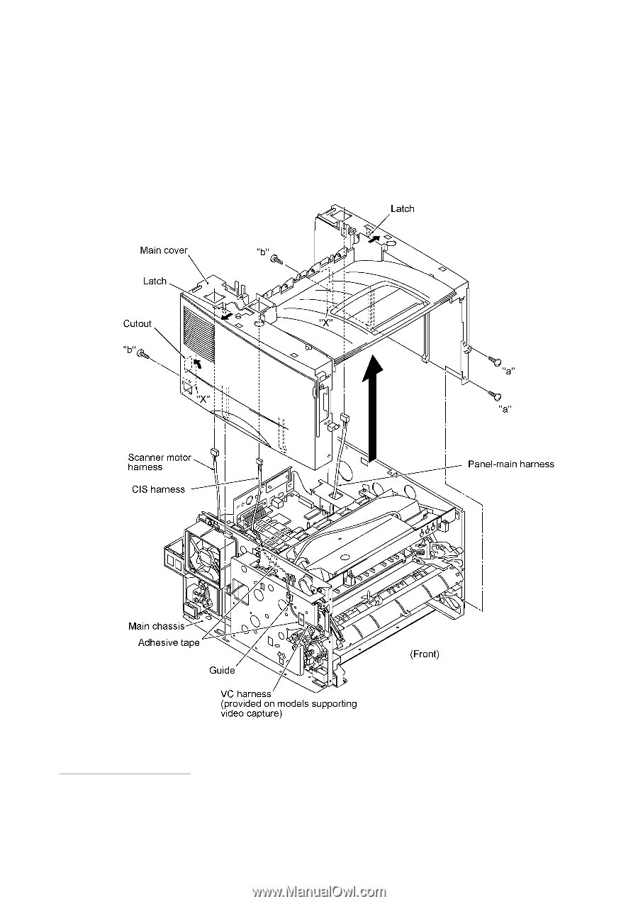
1.14 Main Cover (1) Remove two screws "a" from the front side of the main cover. (2) Remove two screws "b" from the rear side of the main cover, and then pull corner edges "X" outwards to dislocate the main cover from the main chassis. Make sure that the cutout provided in the main cover is dislocated from the power inlet. (3) Unhook the two latches with the tip of a flat screwdriver, then lift up the main cover. "a" and "b": Taptite, bind S M3x8 n Reassembling Notes • When reinstalling the main cover, route the panel-main harness, CIS harness, and scanner motor harness through the respective cutouts provided in the main cover, as illustrated above. IV - 27
-
 1
1 -
2
-
3
-
4
-
5
-
6
-
7
-
8
-
9
-
10
-
11
-
12
-
13
-
14
-
15
-
16
-
17
-
18
-
19
-
20
-
21
-
22
-
23
-
24
-
25
-
26
-
27
-
28
-
29
-
30
-
31
-
32
-
33
-
34
-
35
-
36
-
37
-
38
-
39
-
40
-
41
-
42
-
43
-
44
-
45
-
46
-
47
-
48
-
49
-
50
-
51
-
52
-
53
-
54
-
55
-
56
-
57
-
58
-
59
-
60
-
61
-
62
-
 63
63 -
 64
64 -
 65
65 -
 66
66 -
 67
67 -
 68
68 -
 69
69 -
 70
70 -
 71
71 -
 72
72 -
 73
73 -
74
-
75
-
76
-
77
-
78
-
79
-
80
-
81
-
82
-
83
-
84
-
85
-
86
-
87
-
88
-
89
-
90
-
91
-
92
-
93
-
94
-
95
-
96
-
97
-
98
-
99
-
100
-
101
-
102
-
103
-
104
-
105
-
106
-
107
-
108
-
109
-
110
-
111
-
112
-
113
-
114
-
115
-
116
-
117
-
118
-
119
-
120
-
121
-
122
-
123
-
124
-
125
-
126
-
127
-
128
-
129
-
130
-
131
-
132
-
133
-
134
-
135
-
136
-
137
-
138
-
139
-
140
-
141
-
142
-
143
-
144
-
145
-
146
-
147
-
148
-
149
-
150
-
151
-
152
-
153
-
154
-
155
-
156
-
157
-
158
-
159
-
160
-
161
-
162
-
163
-
164
-
165
-
166
-
167
-
168
-
169
-
170
-
171
-
172
-
173
-
174
-
175
-
176
-
177
-
178
-
179
-
180
-
181
-
182
-
183
-
184
-
185
-
186
-
187
-
188
-
189
-
190
-
191
-
192
-
193
-
194
-
195
-
196
-
197
-
198
-
199
-
200
-
201
-
202
-
203
-
204
-
205
-
206
-
207
-
208
-
209
-
210
-
211
-
212
-
213
-
214
-
215
-
216
-
217
-
218
-
219
-
220
-
221
-
222
-
223
-
224
-
225
-
226
-
227
-
228
-
229
-
230
-
231
-
232
-
233
-
234
-
235
-
236
-
237
-
238
-
239
 |
 |
IV
- 27
1.14
Main Cover
(1)
Remove two screws "a" from the front side of the main cover.
(2)
Remove two screws "b" from the rear side of the main cover, and then pull corner edges "X"
outwards to dislocate the main cover from the main chassis.
Make sure that the cutout
provided in the main cover is dislocated from the power inlet.
(3)
Unhook the two latches with the tip of a flat screwdriver, then lift up the main cover.
n
Reassembling Notes
•
When reinstalling the main cover, route the panel-main harness, CIS harness, and scanner
motor harness through the respective cutouts provided in the main cover, as illustrated above.
"a" and "b":
Taptite, bind S M3x8