Brother International MFC 8500 Service Manual - Page 209
Selectors 1 through 3 are applicable only to models equipped with a flat-bed scanner.
 |
UPC - 012502603832
View all Brother International MFC 8500 manuals
Add to My Manuals
Save this manual to your list of manuals |
Page 209 highlights
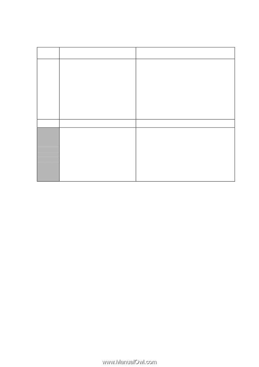
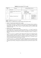
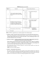
Selector No. 1 | 3 4 5 | 8 WSW41 (CCD fluorescent lamp and modem attenuator, in V. 34 mode) Function Setting and Specifications ON-duration of the fluorescent lamp built in the CCD unit Not used. Modem attenuator No. 1 2 3 000 : 001 : 010 : 011 : 100 : 101 : 110 : 111 : No. 5 6 7 8 0 00 0 0 00 1 0 01 0 0 01 1 0 10 0 | 1 11 1 16 hours 24 hours 12 hours 8 hours 4 hours 2 hours 10 minutes 0 minute : -10 dBm : -11 dBm : -12 dBm : -13 dBm : -14 dBm | : -25 dBm NOTE: WSW41 takes effect only in V. 34 mode. NOTE: Selectors 1 through 3 are applicable only to models equipped with a flat-bed scanner. Selectors 1 through 3: ON-duration of the fluorescent lamp built in the CCD unit If the scanning operation is started when the fluorescent lamp is off, then the lamp will come on and stay on for the time length specified by these selectors. If these selectors are set to "1, 1, 1," the fluorescent lamp will go off after the scanning sequence. Selectors 5 through 8: Modem attenuator These selectors are used to adjust the transmitting level of the modem when the reception level at the remote station is improper due to line loss. This function applies to super G3 protocol signals. 42
-
 1
1 -
2
-
3
-
4
-
5
-
6
-
7
-
8
-
9
-
10
-
11
-
12
-
13
-
14
-
15
-
16
-
17
-
18
-
19
-
20
-
21
-
22
-
23
-
24
-
25
-
26
-
27
-
28
-
29
-
30
-
31
-
32
-
33
-
34
-
35
-
36
-
37
-
38
-
39
-
40
-
41
-
42
-
43
-
44
-
45
-
46
-
47
-
48
-
49
-
50
-
51
-
52
-
53
-
54
-
55
-
56
-
57
-
58
-
59
-
60
-
61
-
62
-
63
-
64
-
65
-
66
-
67
-
68
-
69
-
70
-
71
-
72
-
73
-
74
-
75
-
76
-
77
-
78
-
79
-
80
-
81
-
82
-
83
-
84
-
85
-
86
-
87
-
88
-
89
-
90
-
91
-
92
-
93
-
94
-
95
-
96
-
97
-
98
-
99
-
100
-
101
-
102
-
103
-
104
-
105
-
106
-
107
-
108
-
109
-
110
-
111
-
112
-
113
-
114
-
115
-
116
-
117
-
118
-
119
-
120
-
121
-
122
-
123
-
124
-
125
-
126
-
127
-
128
-
129
-
130
-
131
-
132
-
133
-
134
-
135
-
136
-
137
-
138
-
139
-
140
-
141
-
142
-
143
-
144
-
145
-
146
-
147
-
148
-
149
-
150
-
151
-
152
-
153
-
154
-
155
-
156
-
157
-
158
-
159
-
160
-
161
-
162
-
163
-
164
-
165
-
166
-
167
-
168
-
169
-
170
-
171
-
172
-
173
-
174
-
175
-
176
-
177
-
178
-
179
-
180
-
181
-
182
-
183
-
184
-
185
-
186
-
187
-
188
-
189
-
190
-
191
-
192
-
193
-
194
-
195
-
196
-
197
-
198
-
199
-
200
-
201
-
202
-
203
-
 204
204 -
 205
205 -
 206
206 -
 207
207 -
 208
208 -
 209
209 -
 210
210 -
 211
211 -
 212
212 -
 213
213 -
 214
214 -
215
-
216
-
217
-
218
-
219
-
220
-
221
-
222
-
223
-
224
-
225
-
226
-
227
-
228
-
229
-
230
-
231
-
232
-
233
-
234
-
235
-
236
-
237
-
238
-
239
 |
 |