Brother International MFC 8500 Service Manual - Page 97
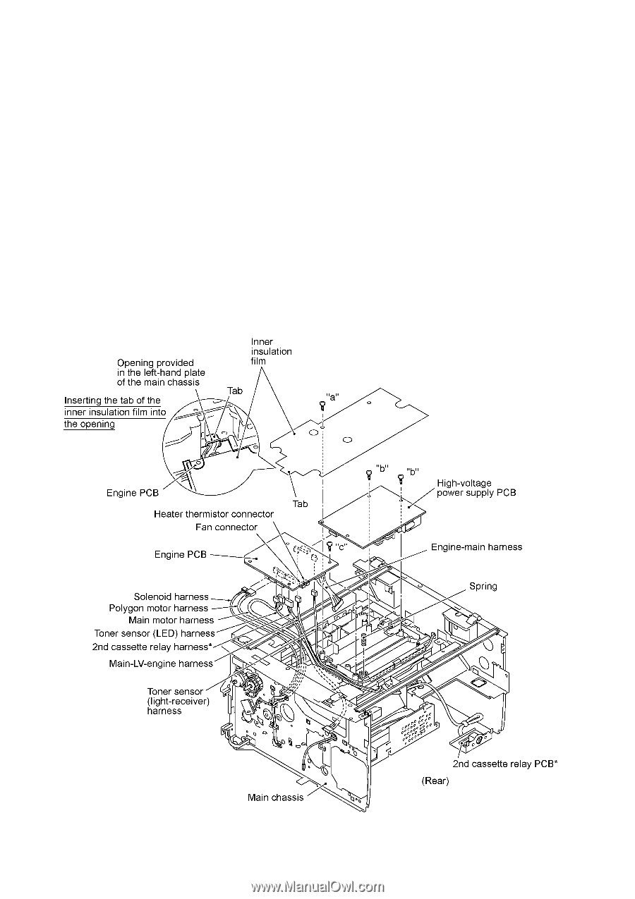
Inner Insulation Film, High-voltage Power Supply PCB, Engine PCB, and 2nd Cassette Relay PCB*
 |
UPC - 012502603832
View all Brother International MFC 8500 manuals
Add to My Manuals
Save this manual to your list of manuals |
Page 97 highlights
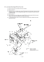
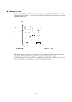
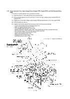
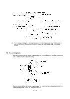
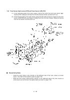
1.23 Inner Insulation Film, High-voltage Power Supply PCB, Engine PCB, and 2nd Cassette Relay PCB* (*Provided on models available with a 2nd paper cassette) (1) Remove screw "a" and take off the inner insulation film. (2) Remove three screws (two "b" and one "c") from the high-voltage power supply PCB and engine PCB. (3) Slightly lift up the high-voltage power supply PCB and disconnect it from the engine PCB. (4) Pull the spring up and out. (5) Slightly hold up the engine PCB and disconnect the following harnesses: • Toner sensor (light-receiver) harness (3-pin, P1) • Main-LV-engine harness (2-pin, P15) • 2nd cassette relay harness* (8-pin, P8) • Heater thermistor harness (2-pin, P6), if the heat-fixing unit has not been removed • Fan harness (2-pin, P7), if the fan has not been removed • Toner sensor (LED) harness (4-pin, P10) • Main motor harness (6-pin, P9) • Polygon motor harness (5-pin, P12) • Solenoid harness (2-pin, P13) "a," "b," and "c": Taptite, bind B M4x12 IV - 56
-
 1
1 -
2
-
3
-
4
-
5
-
6
-
7
-
8
-
9
-
10
-
11
-
12
-
13
-
14
-
15
-
16
-
17
-
18
-
19
-
20
-
21
-
22
-
23
-
24
-
25
-
26
-
27
-
28
-
29
-
30
-
31
-
32
-
33
-
34
-
35
-
36
-
37
-
38
-
39
-
40
-
41
-
42
-
43
-
44
-
45
-
46
-
47
-
48
-
49
-
50
-
51
-
52
-
53
-
54
-
55
-
56
-
57
-
58
-
59
-
60
-
61
-
62
-
63
-
64
-
65
-
66
-
67
-
68
-
69
-
70
-
71
-
72
-
73
-
74
-
75
-
76
-
77
-
78
-
79
-
80
-
81
-
82
-
83
-
84
-
85
-
86
-
87
-
88
-
89
-
90
-
91
-
 92
92 -
 93
93 -
 94
94 -
 95
95 -
 96
96 -
 97
97 -
 98
98 -
 99
99 -
 100
100 -
 101
101 -
 102
102 -
103
-
104
-
105
-
106
-
107
-
108
-
109
-
110
-
111
-
112
-
113
-
114
-
115
-
116
-
117
-
118
-
119
-
120
-
121
-
122
-
123
-
124
-
125
-
126
-
127
-
128
-
129
-
130
-
131
-
132
-
133
-
134
-
135
-
136
-
137
-
138
-
139
-
140
-
141
-
142
-
143
-
144
-
145
-
146
-
147
-
148
-
149
-
150
-
151
-
152
-
153
-
154
-
155
-
156
-
157
-
158
-
159
-
160
-
161
-
162
-
163
-
164
-
165
-
166
-
167
-
168
-
169
-
170
-
171
-
172
-
173
-
174
-
175
-
176
-
177
-
178
-
179
-
180
-
181
-
182
-
183
-
184
-
185
-
186
-
187
-
188
-
189
-
190
-
191
-
192
-
193
-
194
-
195
-
196
-
197
-
198
-
199
-
200
-
201
-
202
-
203
-
204
-
205
-
206
-
207
-
208
-
209
-
210
-
211
-
212
-
213
-
214
-
215
-
216
-
217
-
218
-
219
-
220
-
221
-
222
-
223
-
224
-
225
-
226
-
227
-
228
-
229
-
230
-
231
-
232
-
233
-
234
-
235
-
236
-
237
-
238
-
239
 |
 |