Brother International MFC 8500 Service Manual - Page 124
Operational Check of LCD, 3.7 Operational Check of Control Panel PCB, Function
 |
UPC - 012502603832
View all Brother International MFC 8500 manuals
Add to My Manuals
Save this manual to your list of manuals |
Page 124 highlights
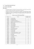
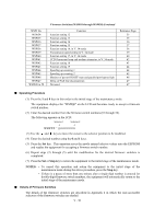
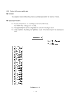
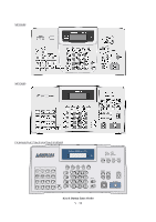
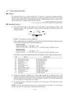
3.6 Operational Check of LCD n Function This function allows you to check whether the LCD on the control panel works normally. n Operating Procedure (1) Press the 1 and 2 keys in this order in the initial stage of the maintenance mode. The LCD shows (2) Press the Fax Start key. Each time you press the Fax Start key, the LCD cycles through the displays shown at right. (3) Press the Stop key in any process of the above display cycle. The equipment beeps for one second and returns to the initial stage of the maintenance mode. 3.7 Operational Check of Control Panel PCB n Function This function allows you to check the control panel PCB for normal operation. n Operating Procedure (1) Press the 1 and 3 keys in this order in the initial stage of the maintenance mode. The "00 " will appear on the LCD. (2) Press the keys and buttons in the order designated in the illustration shown below. The LCD shows the corresponding number in decimal notation each time a key or button is pressed. Check that the displayed number is correct by referring to the illustration below. If a key or button is pressed out of order, the equipment beeps and displays the "INVALID OPERATE" on the LCD. To return to the status ready to accept key & button entry for operational check, press the Stop key. (3) After the last number key or button is pressed, the equipment beeps and returns to the initial stage of the maintenance mode. To terminate this operation, press the Stop key. The equipment returns to the initial stage of the maintenance mode. V - 12
-
 1
1 -
2
-
3
-
4
-
5
-
6
-
7
-
8
-
9
-
10
-
11
-
12
-
13
-
14
-
15
-
16
-
17
-
18
-
19
-
20
-
21
-
22
-
23
-
24
-
25
-
26
-
27
-
28
-
29
-
30
-
31
-
32
-
33
-
34
-
35
-
36
-
37
-
38
-
39
-
40
-
41
-
42
-
43
-
44
-
45
-
46
-
47
-
48
-
49
-
50
-
51
-
52
-
53
-
54
-
55
-
56
-
57
-
58
-
59
-
60
-
61
-
62
-
63
-
64
-
65
-
66
-
67
-
68
-
69
-
70
-
71
-
72
-
73
-
74
-
75
-
76
-
77
-
78
-
79
-
80
-
81
-
82
-
83
-
84
-
85
-
86
-
87
-
88
-
89
-
90
-
91
-
92
-
93
-
94
-
95
-
96
-
97
-
98
-
99
-
100
-
101
-
102
-
103
-
104
-
105
-
106
-
107
-
108
-
109
-
110
-
111
-
112
-
113
-
114
-
115
-
116
-
117
-
118
-
 119
119 -
 120
120 -
 121
121 -
 122
122 -
 123
123 -
 124
124 -
 125
125 -
 126
126 -
 127
127 -
 128
128 -
 129
129 -
130
-
131
-
132
-
133
-
134
-
135
-
136
-
137
-
138
-
139
-
140
-
141
-
142
-
143
-
144
-
145
-
146
-
147
-
148
-
149
-
150
-
151
-
152
-
153
-
154
-
155
-
156
-
157
-
158
-
159
-
160
-
161
-
162
-
163
-
164
-
165
-
166
-
167
-
168
-
169
-
170
-
171
-
172
-
173
-
174
-
175
-
176
-
177
-
178
-
179
-
180
-
181
-
182
-
183
-
184
-
185
-
186
-
187
-
188
-
189
-
190
-
191
-
192
-
193
-
194
-
195
-
196
-
197
-
198
-
199
-
200
-
201
-
202
-
203
-
204
-
205
-
206
-
207
-
208
-
209
-
210
-
211
-
212
-
213
-
214
-
215
-
216
-
217
-
218
-
219
-
220
-
221
-
222
-
223
-
224
-
225
-
226
-
227
-
228
-
229
-
230
-
231
-
232
-
233
-
234
-
235
-
236
-
237
-
238
-
239
 |
 |