Brother International MFC 8500 Service Manual - Page 184
Attenuation in the high-band frequency is greater than in the low-band frequency.
 |
UPC - 012502603832
View all Brother International MFC 8500 manuals
Add to My Manuals
Save this manual to your list of manuals |
Page 184 highlights
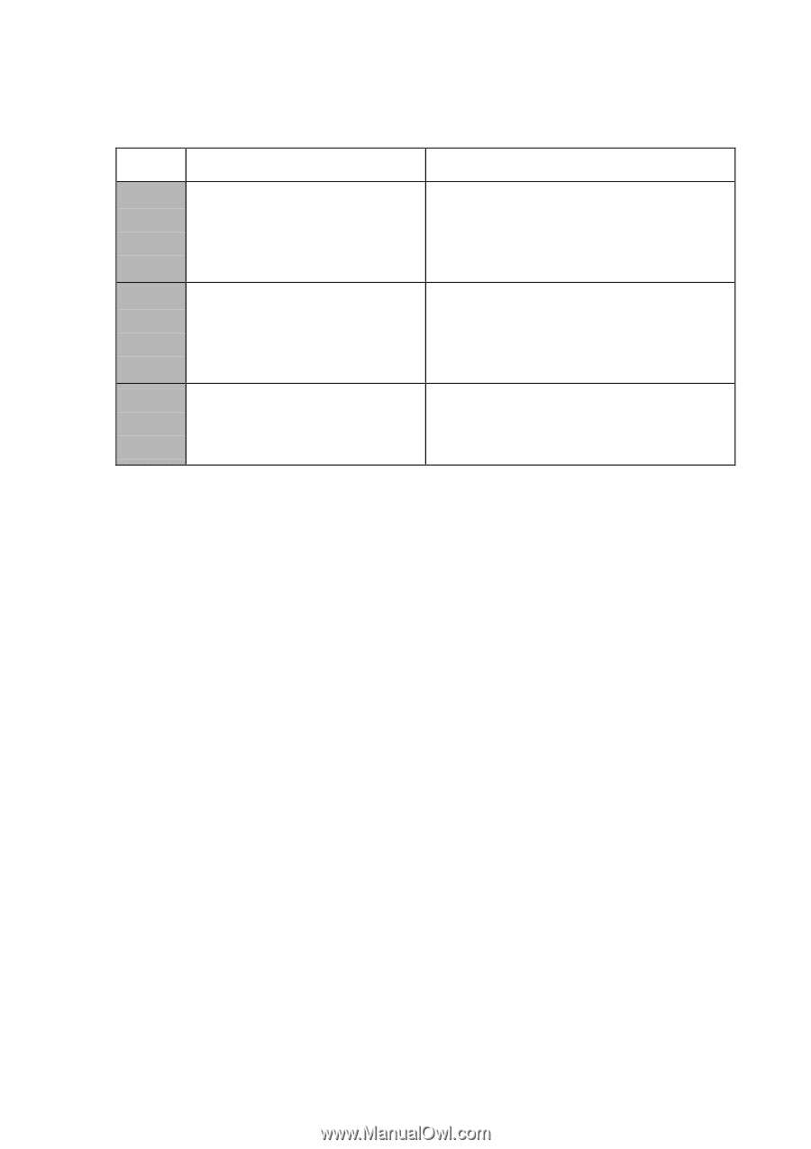
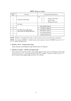
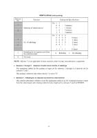
Selector No. 1 2 3 4 5 | 8 WSW13 (Modem setting) Function Cable equalizer Reception level Modem attenuator Setting and Specifications No. 1 2 00 : 01 : 10 : 11 : No. 3 4 00 : 01 : 10 : 11 : 0: 0 dB 0: 0 dB 0: 0 dB 0: 0 dB 0 km 1.8 km 3.6 km 5.6 km -43 dBm -47 dBm -49 dBm -51 dBm 1: 8 dB 1: 4 dB 1: 2 dB 1: 1 dB The modem should be adjusted according to the user's line conditions. Selectors 1 and 2: Cable equalizer These selectors are used to improve the pass-band characteristics of analogue signals on a line. (Attenuation in the high-band frequency is greater than in the low-band frequency.) Set these selectors according to the distance from the telephone switchboard to the facsimile equipment. Selectors 3 and 4: Reception level These selectors set the optimum receive signal level. Selectors 5 through 8: Modem attenuator These selectors are used to adjust the transmitting level of the modem when the reception level at the remote station is improper due to line loss. This function applies to G3 protocol signals. Setting two or more selectors to "1" produces addition of attenuation assigned to each selector. This setting will be limited if selector 8 of WSW23 is set to "0." 17
-
 1
1 -
2
-
3
-
4
-
5
-
6
-
7
-
8
-
9
-
10
-
11
-
12
-
13
-
14
-
15
-
16
-
17
-
18
-
19
-
20
-
21
-
22
-
23
-
24
-
25
-
26
-
27
-
28
-
29
-
30
-
31
-
32
-
33
-
34
-
35
-
36
-
37
-
38
-
39
-
40
-
41
-
42
-
43
-
44
-
45
-
46
-
47
-
48
-
49
-
50
-
51
-
52
-
53
-
54
-
55
-
56
-
57
-
58
-
59
-
60
-
61
-
62
-
63
-
64
-
65
-
66
-
67
-
68
-
69
-
70
-
71
-
72
-
73
-
74
-
75
-
76
-
77
-
78
-
79
-
80
-
81
-
82
-
83
-
84
-
85
-
86
-
87
-
88
-
89
-
90
-
91
-
92
-
93
-
94
-
95
-
96
-
97
-
98
-
99
-
100
-
101
-
102
-
103
-
104
-
105
-
106
-
107
-
108
-
109
-
110
-
111
-
112
-
113
-
114
-
115
-
116
-
117
-
118
-
119
-
120
-
121
-
122
-
123
-
124
-
125
-
126
-
127
-
128
-
129
-
130
-
131
-
132
-
133
-
134
-
135
-
136
-
137
-
138
-
139
-
140
-
141
-
142
-
143
-
144
-
145
-
146
-
147
-
148
-
149
-
150
-
151
-
152
-
153
-
154
-
155
-
156
-
157
-
158
-
159
-
160
-
161
-
162
-
163
-
164
-
165
-
166
-
167
-
168
-
169
-
170
-
171
-
172
-
173
-
174
-
175
-
176
-
177
-
178
-
 179
179 -
 180
180 -
 181
181 -
 182
182 -
 183
183 -
 184
184 -
 185
185 -
 186
186 -
 187
187 -
 188
188 -
 189
189 -
190
-
191
-
192
-
193
-
194
-
195
-
196
-
197
-
198
-
199
-
200
-
201
-
202
-
203
-
204
-
205
-
206
-
207
-
208
-
209
-
210
-
211
-
212
-
213
-
214
-
215
-
216
-
217
-
218
-
219
-
220
-
221
-
222
-
223
-
224
-
225
-
226
-
227
-
228
-
229
-
230
-
231
-
232
-
233
-
234
-
235
-
236
-
237
-
238
-
239
 |
 |