Brother International MFC 8500 Service Manual - Page 36
Sensors and Actuators, Toner sensor LED PCB
 |
UPC - 012502603832
View all Brother International MFC 8500 manuals
Add to My Manuals
Save this manual to your list of manuals |
Page 36 highlights
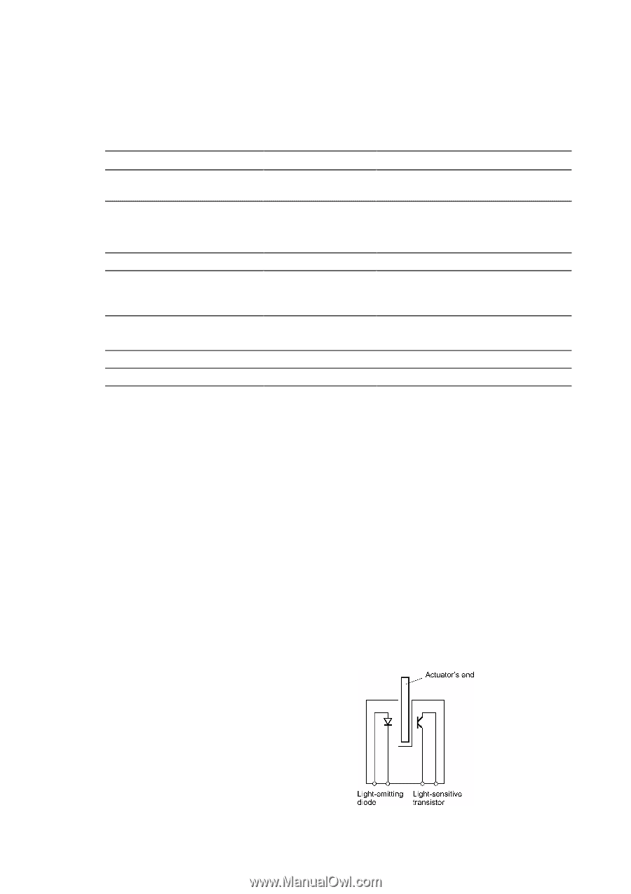
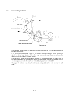
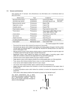
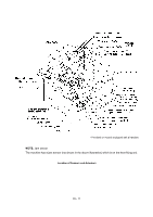
2.3 Sensors and Actuators This machine has 12 sensors: nine photosensors, two thermistors and a mechanical switch as described below. Sensor name Document front sensor Document rear sensor Manual insertion sensor Registration sensor Cassette sensor Paper ejection sensor Toner sensor Cover sensor Jam sensor Heater thermistor In-casing temperature sensor Hook switch* Type Photosensor Photosensor Photosensor Photosensor Photosensor Photosensor Photosensor Photosensor Photosensor Thermistor Thermistor Mechanical switch Located on Control panel PCB Document sensor PCB Control panel PCB ASSY Engine PCB Engine PCB Engine PCB Paper ejection sensor PCB Toner sensor (LED) PCB and toner sensor (light-receiver) PCB Toner sensor (LED) PCB Heat-fixing unit Heat-fixing unit Left-hand plate of the main chassis Hook switch PCB* *For models equipped with a handset • Document front sensor which detects the presence of documents. • Document rear sensor which detects the leading and trailing edges of pages to tell the control circuitry when the leading edge of a new page has reached the starting position and when the scan for that page is over. • Manual insertion sensor which detects whether paper is inserted manually through the paper slot or whether paper fed through the paper cassette has jammed. • Registration sensor which detects the leading and trailing edges of recording paper, which allows the controller to determine the registration timing and check paper jam. • Cassette sensor which detects whether the paper cassette is loaded. • Paper ejection sensor which detects whether the recording paper goes out of the equipment. • Toner sensor which detects whether there is toner or a toner cartridge is loaded. • Cover sensor which detects whether the front cover is closed. • Jam sensor which detects whether paper is jammed inside the heat-fixing unit. • Heater thermistor which allows the controller to monitor the temperature of the heater roller of the fixing unit. • In-casing temperature sensor which allows the controller to monitor the temperature inside the equipment. • Hook switch* which detects whether the handset is placed on the handset mount*. The above photosensors are a photointerrupter consisting of a light-emitting diode and a light-sensitive transistor. Each of them has an actuator separately arranged as shown on the next page. III - 10
-
 1
1 -
2
-
3
-
4
-
5
-
6
-
7
-
8
-
9
-
10
-
11
-
12
-
13
-
14
-
15
-
16
-
17
-
18
-
19
-
20
-
21
-
22
-
23
-
24
-
25
-
26
-
27
-
28
-
29
-
30
-
 31
31 -
 32
32 -
 33
33 -
 34
34 -
 35
35 -
 36
36 -
 37
37 -
 38
38 -
 39
39 -
 40
40 -
 41
41 -
42
-
43
-
44
-
45
-
46
-
47
-
48
-
49
-
50
-
51
-
52
-
53
-
54
-
55
-
56
-
57
-
58
-
59
-
60
-
61
-
62
-
63
-
64
-
65
-
66
-
67
-
68
-
69
-
70
-
71
-
72
-
73
-
74
-
75
-
76
-
77
-
78
-
79
-
80
-
81
-
82
-
83
-
84
-
85
-
86
-
87
-
88
-
89
-
90
-
91
-
92
-
93
-
94
-
95
-
96
-
97
-
98
-
99
-
100
-
101
-
102
-
103
-
104
-
105
-
106
-
107
-
108
-
109
-
110
-
111
-
112
-
113
-
114
-
115
-
116
-
117
-
118
-
119
-
120
-
121
-
122
-
123
-
124
-
125
-
126
-
127
-
128
-
129
-
130
-
131
-
132
-
133
-
134
-
135
-
136
-
137
-
138
-
139
-
140
-
141
-
142
-
143
-
144
-
145
-
146
-
147
-
148
-
149
-
150
-
151
-
152
-
153
-
154
-
155
-
156
-
157
-
158
-
159
-
160
-
161
-
162
-
163
-
164
-
165
-
166
-
167
-
168
-
169
-
170
-
171
-
172
-
173
-
174
-
175
-
176
-
177
-
178
-
179
-
180
-
181
-
182
-
183
-
184
-
185
-
186
-
187
-
188
-
189
-
190
-
191
-
192
-
193
-
194
-
195
-
196
-
197
-
198
-
199
-
200
-
201
-
202
-
203
-
204
-
205
-
206
-
207
-
208
-
209
-
210
-
211
-
212
-
213
-
214
-
215
-
216
-
217
-
218
-
219
-
220
-
221
-
222
-
223
-
224
-
225
-
226
-
227
-
228
-
229
-
230
-
231
-
232
-
233
-
234
-
235
-
236
-
237
-
238
-
239
 |
 |