Brother International MFC 8500 Service Manual - Page 44
Disassembly Order Flow, set F/R, and gear 20 F/R - parts manual
 |
UPC - 012502603832
View all Brother International MFC 8500 manuals
Add to My Manuals
Save this manual to your list of manuals |
Page 44 highlights
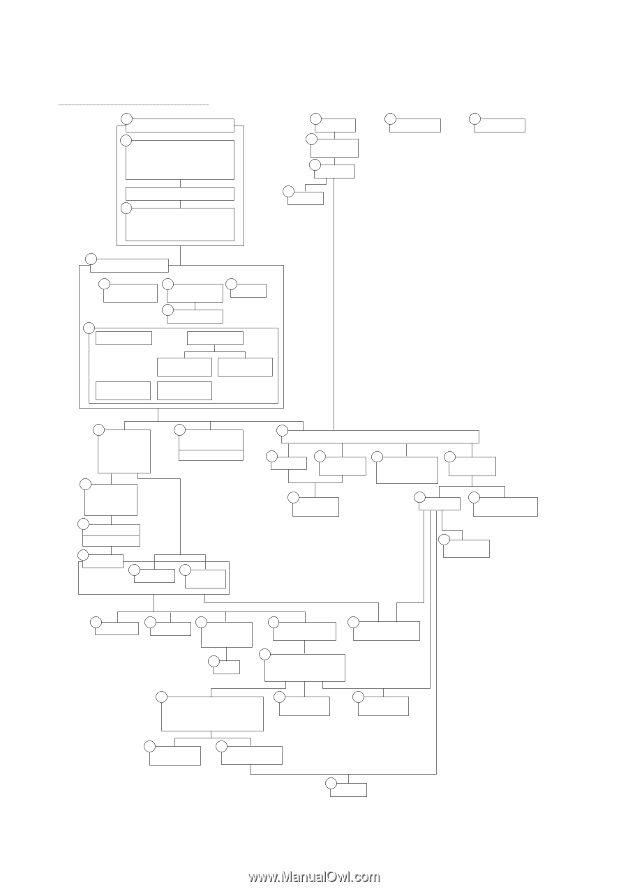
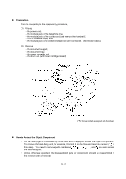
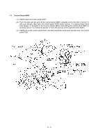
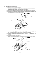
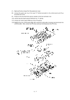
n Disassembly Order Flow 1.3 Control panel ASSY 1.4 Panel rear cover - ADF parts - NIP-related parts - Document pressure bar - Document rear sensor actuator Document front sensor actuator 1.4 Control panel - Control panel PCB ASSY (NOTE 1) - FPC key - LCD 1.7 Scanner frame ASSY 1.5 Document feed roller ASSY 1.7 Scanner motor 1.5 1.6 Document ejection CIS unit roller ASSY 1.5 Pinch rollers Scanner drive unit Pressure rollers and leaf springs Document take-in roller Control panel locks Separation roller 1.1 Rear cover 1.2 Access plates R and F 1.20 NCU shield 1.10 Paper sub tray 1.28 Paper cassette 1.20 NCU PCB *1 Provided on those models equipped with handset. *2 Provided on those models without handset. *3 Provided on those models supporting video capture. *4 Provided on those models not supporting video capture. *5 Provided on those models available with a 2nd paper cassette (as an option or standard). (NOTE 1) The control panel PCB ASSY consists of a control panel PCB and document sensor PCB. On the former PCB is the document front sensor; on the latter PCB is the document rear sensor. (NOTE 2) On the hook switch PCB is the hook switch sensor (mechanical switch). (NOTE 3) On the heat-fixing unit are a jam sensor and heater thermistor. (NOTE 4) The main PCB monitors the internal resistance of the in-casing temperature sensor (thermistor) attached to the main chassis. (NOTE 5) On the paper ejection sensor PCB is the paper ejection sensor (photosensor). (NOTE 6) On the engine PCB are these photosensors: - Registration sensor - Manual insertion sensor - Cassette sensor (NOTE 7) On the toner sensor (light-receiver) PCB is a light-sensitive transistor. (NOTE 8) On the toner sensor (LED) PCB are an LED and cover sensor (photosensor). 1.8 Top cover - Exit roller - Speaker - Document guides 1.11 1.9 1.21 Handset mount and (NOTE 2) hook switch PCB *1 Bottom plate Side cover *2 1.21 1.21 1.22 Main PCB Paper ejection Low-voltage power sensor PCB supply PCB and (NOTE 4) (NOTE 5) power inlet 1.23 Inner insulation film VC cover, VC bracket, and VC connector PCB *3 1.21 Bottom insulation film 1.23 1.23 Engine PCB High-voltage power supply PCB (NOTE 6) 1.12 Front cover Front sub cover *4 1.14 Main cover 1.232nd cassette relay PCB *5 1.13 1.13 Outer chute Paper pinch rollers 1.15 1.16 Switch cover Laser unit 1.17 Heat-fixing unit - Heater roller - FU lamp (NOTE 3) 1.18 Fan 1.19 Drive gear ASSY - Main motor ASSY 1.19 Develop joint and front cover link (as cover sensor actuator) 1.24 Toner sensor (lightreceiver) PCB (NOTE 7) 1.25 Gears (Inner gear 54, gear 45 set P/R, gear 20 P/R, gear 40/54, gear 45 set F/R, and gear 20 F/R) 1.26 Paper feed roller ASSY 1.24 Toner sensor (LED) PCB (NOTE 8) 1.25 Paper pick-up roller 1.27 Clutch levers and cassette guide L 1.27 Solenoid IV - 3
-
 1
1 -
2
-
3
-
4
-
5
-
6
-
7
-
8
-
9
-
10
-
11
-
12
-
13
-
14
-
15
-
16
-
17
-
18
-
19
-
20
-
21
-
22
-
23
-
24
-
25
-
26
-
27
-
28
-
29
-
30
-
31
-
32
-
33
-
34
-
35
-
36
-
37
-
38
-
 39
39 -
 40
40 -
 41
41 -
 42
42 -
 43
43 -
 44
44 -
 45
45 -
 46
46 -
 47
47 -
 48
48 -
 49
49 -
50
-
51
-
52
-
53
-
54
-
55
-
56
-
57
-
58
-
59
-
60
-
61
-
62
-
63
-
64
-
65
-
66
-
67
-
68
-
69
-
70
-
71
-
72
-
73
-
74
-
75
-
76
-
77
-
78
-
79
-
80
-
81
-
82
-
83
-
84
-
85
-
86
-
87
-
88
-
89
-
90
-
91
-
92
-
93
-
94
-
95
-
96
-
97
-
98
-
99
-
100
-
101
-
102
-
103
-
104
-
105
-
106
-
107
-
108
-
109
-
110
-
111
-
112
-
113
-
114
-
115
-
116
-
117
-
118
-
119
-
120
-
121
-
122
-
123
-
124
-
125
-
126
-
127
-
128
-
129
-
130
-
131
-
132
-
133
-
134
-
135
-
136
-
137
-
138
-
139
-
140
-
141
-
142
-
143
-
144
-
145
-
146
-
147
-
148
-
149
-
150
-
151
-
152
-
153
-
154
-
155
-
156
-
157
-
158
-
159
-
160
-
161
-
162
-
163
-
164
-
165
-
166
-
167
-
168
-
169
-
170
-
171
-
172
-
173
-
174
-
175
-
176
-
177
-
178
-
179
-
180
-
181
-
182
-
183
-
184
-
185
-
186
-
187
-
188
-
189
-
190
-
191
-
192
-
193
-
194
-
195
-
196
-
197
-
198
-
199
-
200
-
201
-
202
-
203
-
204
-
205
-
206
-
207
-
208
-
209
-
210
-
211
-
212
-
213
-
214
-
215
-
216
-
217
-
218
-
219
-
220
-
221
-
222
-
223
-
224
-
225
-
226
-
227
-
228
-
229
-
230
-
231
-
232
-
233
-
234
-
235
-
236
-
237
-
238
-
239
 |
 |