Brother International MFC 8500 Service Manual - Page 70
Laser Unit, Do not disturb it.
 |
UPC - 012502603832
View all Brother International MFC 8500 manuals
Add to My Manuals
Save this manual to your list of manuals |
Page 70 highlights
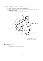
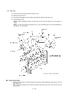
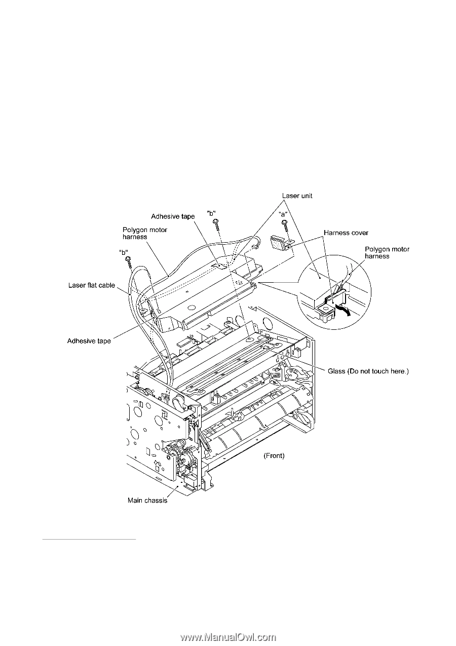
1.16 Laser Unit (1) Remove screw "a" and take off the harness cover. (2) Remove two screws "b." (3) Disconnect the polygon motor harness and laser flat cable from the laser unit. (4) Lift up the laser unit. NOTE: When handling the laser unit, take care not to touch the inside of the unit, glass, or mirror. NOTE: On the small PCB in the laser unit is a 2-pin connector which is for the adjustment in the factory. Do not disturb it. "a" and "b": Taptite, cup S M3x16 n Reassembling Notes • Before putting the laser unit back into place, check for any toner particles, paper dust or dirt, and clean them out. • After routing the polygon motor harness and laser flat cable, tape them onto the laser unit as shown above. IV - 29
-
 1
1 -
2
-
3
-
4
-
5
-
6
-
7
-
8
-
9
-
10
-
11
-
12
-
13
-
14
-
15
-
16
-
17
-
18
-
19
-
20
-
21
-
22
-
23
-
24
-
25
-
26
-
27
-
28
-
29
-
30
-
31
-
32
-
33
-
34
-
35
-
36
-
37
-
38
-
39
-
40
-
41
-
42
-
43
-
44
-
45
-
46
-
47
-
48
-
49
-
50
-
51
-
52
-
53
-
54
-
55
-
56
-
57
-
58
-
59
-
60
-
61
-
62
-
63
-
64
-
 65
65 -
 66
66 -
 67
67 -
 68
68 -
 69
69 -
 70
70 -
 71
71 -
 72
72 -
 73
73 -
 74
74 -
 75
75 -
76
-
77
-
78
-
79
-
80
-
81
-
82
-
83
-
84
-
85
-
86
-
87
-
88
-
89
-
90
-
91
-
92
-
93
-
94
-
95
-
96
-
97
-
98
-
99
-
100
-
101
-
102
-
103
-
104
-
105
-
106
-
107
-
108
-
109
-
110
-
111
-
112
-
113
-
114
-
115
-
116
-
117
-
118
-
119
-
120
-
121
-
122
-
123
-
124
-
125
-
126
-
127
-
128
-
129
-
130
-
131
-
132
-
133
-
134
-
135
-
136
-
137
-
138
-
139
-
140
-
141
-
142
-
143
-
144
-
145
-
146
-
147
-
148
-
149
-
150
-
151
-
152
-
153
-
154
-
155
-
156
-
157
-
158
-
159
-
160
-
161
-
162
-
163
-
164
-
165
-
166
-
167
-
168
-
169
-
170
-
171
-
172
-
173
-
174
-
175
-
176
-
177
-
178
-
179
-
180
-
181
-
182
-
183
-
184
-
185
-
186
-
187
-
188
-
189
-
190
-
191
-
192
-
193
-
194
-
195
-
196
-
197
-
198
-
199
-
200
-
201
-
202
-
203
-
204
-
205
-
206
-
207
-
208
-
209
-
210
-
211
-
212
-
213
-
214
-
215
-
216
-
217
-
218
-
219
-
220
-
221
-
222
-
223
-
224
-
225
-
226
-
227
-
228
-
229
-
230
-
231
-
232
-
233
-
234
-
235
-
236
-
237
-
238
-
239
 |
 |
IV
- 29
1.16
Laser Unit
(1)
Remove screw "a" and take off the harness cover.
(2)
Remove two screws "b."
(3)
Disconnect the polygon motor harness and laser flat cable from the laser unit.
(4)
Lift up the laser unit.
NOTE:
When handling the laser unit, take care not to touch the inside of the unit, glass, or
mirror.
NOTE:
On the small PCB in the laser unit is a 2-pin connector which is for the adjustment in
the factory.
Do not disturb it.
n
Reassembling Notes
•
Before putting the laser unit back into place, check for any toner particles, paper dust or dirt, and
clean them out.
•
After routing the polygon motor harness and laser flat cable, tape them onto the laser unit as
shown above.
"a" and "b":
Taptite, cup S M3x16