Brother International MFC 8500 Service Manual - Page 48
Unhook the control panel PCB from three Z latches., Slightly lift up the control panel PCB
 |
UPC - 012502603832
View all Brother International MFC 8500 manuals
Add to My Manuals
Save this manual to your list of manuals |
Page 48 highlights
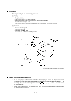
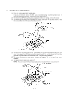
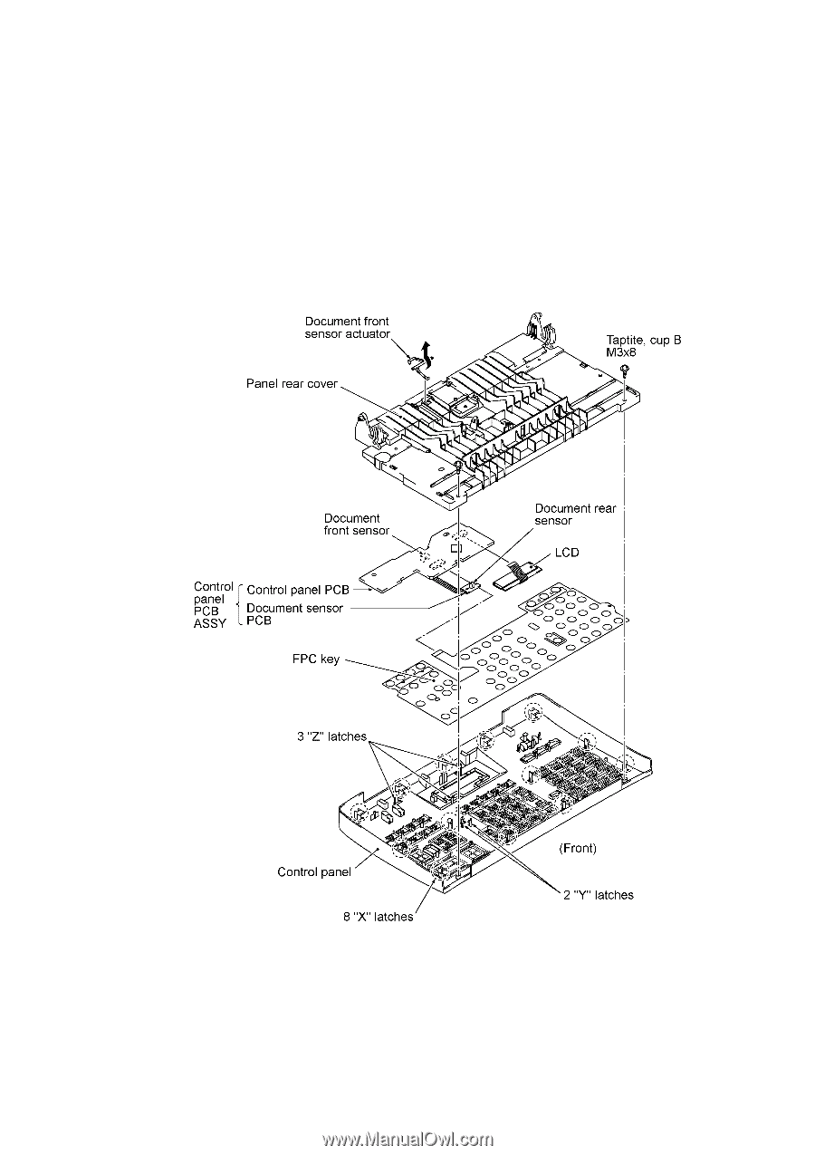
(7) Remove the two screws from the panel rear cover. (8) Unhook the panel rear cover from eight "X" latches provided on the control panel and lift up the panel rear cover. (9) Fully turn the document front sensor actuator to the rear and take it out. (10) Unhook the document sensor PCB from two "Y" latches. (11) Unhook the control panel PCB from three "Z" latches. (12) Slightly lift up the control panel PCB, then unlock the LCD cable connector and disconnect the LCD flat cable. Next, unlock the FPC key connector and disconnect the FPC key. IV - 7
-
 1
1 -
2
-
3
-
4
-
5
-
6
-
7
-
8
-
9
-
10
-
11
-
12
-
13
-
14
-
15
-
16
-
17
-
18
-
19
-
20
-
21
-
22
-
23
-
24
-
25
-
26
-
27
-
28
-
29
-
30
-
31
-
32
-
33
-
34
-
35
-
36
-
37
-
38
-
39
-
40
-
41
-
42
-
 43
43 -
 44
44 -
 45
45 -
 46
46 -
 47
47 -
 48
48 -
 49
49 -
 50
50 -
 51
51 -
 52
52 -
 53
53 -
54
-
55
-
56
-
57
-
58
-
59
-
60
-
61
-
62
-
63
-
64
-
65
-
66
-
67
-
68
-
69
-
70
-
71
-
72
-
73
-
74
-
75
-
76
-
77
-
78
-
79
-
80
-
81
-
82
-
83
-
84
-
85
-
86
-
87
-
88
-
89
-
90
-
91
-
92
-
93
-
94
-
95
-
96
-
97
-
98
-
99
-
100
-
101
-
102
-
103
-
104
-
105
-
106
-
107
-
108
-
109
-
110
-
111
-
112
-
113
-
114
-
115
-
116
-
117
-
118
-
119
-
120
-
121
-
122
-
123
-
124
-
125
-
126
-
127
-
128
-
129
-
130
-
131
-
132
-
133
-
134
-
135
-
136
-
137
-
138
-
139
-
140
-
141
-
142
-
143
-
144
-
145
-
146
-
147
-
148
-
149
-
150
-
151
-
152
-
153
-
154
-
155
-
156
-
157
-
158
-
159
-
160
-
161
-
162
-
163
-
164
-
165
-
166
-
167
-
168
-
169
-
170
-
171
-
172
-
173
-
174
-
175
-
176
-
177
-
178
-
179
-
180
-
181
-
182
-
183
-
184
-
185
-
186
-
187
-
188
-
189
-
190
-
191
-
192
-
193
-
194
-
195
-
196
-
197
-
198
-
199
-
200
-
201
-
202
-
203
-
204
-
205
-
206
-
207
-
208
-
209
-
210
-
211
-
212
-
213
-
214
-
215
-
216
-
217
-
218
-
219
-
220
-
221
-
222
-
223
-
224
-
225
-
226
-
227
-
228
-
229
-
230
-
231
-
232
-
233
-
234
-
235
-
236
-
237
-
238
-
239
 |
 |
IV
- 7
(7)
Remove the two screws from the panel rear cover.
(8)
Unhook the panel rear cover from eight "X" latches provided on the control panel and lift up
the panel rear cover.
(9)
Fully turn the document front sensor actuator to the rear and take it out.
(10)
Unhook the document sensor PCB from two "Y" latches.
(11)
Unhook the control panel PCB from three "Z" latches.
(12)
Slightly lift up the control panel PCB, then unlock the LCD cable connector and disconnect the
LCD flat cable.
Next, unlock the FPC key connector and disconnect the FPC key.