Brother International MFC 8500 Service Manual - Page 95
Low-voltage Power Supply PCB and Power Inlet, Remove screw i.
 |
UPC - 012502603832
View all Brother International MFC 8500 manuals
Add to My Manuals
Save this manual to your list of manuals |
Page 95 highlights
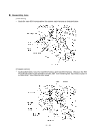
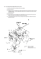
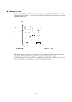
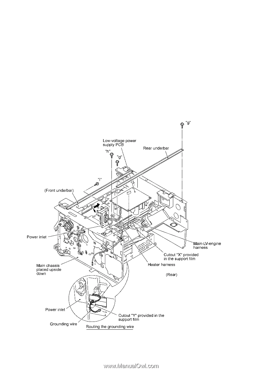
1.22 Low-voltage Power Supply PCB and Power Inlet (1) Remove two screws "g" and take off the rear underbar. (2) Remove screw "h." (3) Slightly lift up the low-voltage power supply PCB and disconnect the heater harness and main- LV-engine harness. The low-voltage power supply PCB is connected to the power inlet with soldered lead wires. (4) Remove screw "i." (5) While holding up the low-voltage power supply PCB, take out the power inlet from the main chassis to the inside in the direction of the arrow shown below. (6) To separate the power inlet from the low-voltage power supply PCB, unsolder the two lead wires from the PCB. "g" and "i": Taptite, cup S M3x6 "h": Taptite, cup S M3x6 (Tightening torque: 0.5 N•m) IV - 54
-
 1
1 -
2
-
3
-
4
-
5
-
6
-
7
-
8
-
9
-
10
-
11
-
12
-
13
-
14
-
15
-
16
-
17
-
18
-
19
-
20
-
21
-
22
-
23
-
24
-
25
-
26
-
27
-
28
-
29
-
30
-
31
-
32
-
33
-
34
-
35
-
36
-
37
-
38
-
39
-
40
-
41
-
42
-
43
-
44
-
45
-
46
-
47
-
48
-
49
-
50
-
51
-
52
-
53
-
54
-
55
-
56
-
57
-
58
-
59
-
60
-
61
-
62
-
63
-
64
-
65
-
66
-
67
-
68
-
69
-
70
-
71
-
72
-
73
-
74
-
75
-
76
-
77
-
78
-
79
-
80
-
81
-
82
-
83
-
84
-
85
-
86
-
87
-
88
-
89
-
 90
90 -
 91
91 -
 92
92 -
 93
93 -
 94
94 -
 95
95 -
 96
96 -
 97
97 -
 98
98 -
 99
99 -
 100
100 -
101
-
102
-
103
-
104
-
105
-
106
-
107
-
108
-
109
-
110
-
111
-
112
-
113
-
114
-
115
-
116
-
117
-
118
-
119
-
120
-
121
-
122
-
123
-
124
-
125
-
126
-
127
-
128
-
129
-
130
-
131
-
132
-
133
-
134
-
135
-
136
-
137
-
138
-
139
-
140
-
141
-
142
-
143
-
144
-
145
-
146
-
147
-
148
-
149
-
150
-
151
-
152
-
153
-
154
-
155
-
156
-
157
-
158
-
159
-
160
-
161
-
162
-
163
-
164
-
165
-
166
-
167
-
168
-
169
-
170
-
171
-
172
-
173
-
174
-
175
-
176
-
177
-
178
-
179
-
180
-
181
-
182
-
183
-
184
-
185
-
186
-
187
-
188
-
189
-
190
-
191
-
192
-
193
-
194
-
195
-
196
-
197
-
198
-
199
-
200
-
201
-
202
-
203
-
204
-
205
-
206
-
207
-
208
-
209
-
210
-
211
-
212
-
213
-
214
-
215
-
216
-
217
-
218
-
219
-
220
-
221
-
222
-
223
-
224
-
225
-
226
-
227
-
228
-
229
-
230
-
231
-
232
-
233
-
234
-
235
-
236
-
237
-
238
-
239
 |
 |
IV
- 54
1.22
Low-voltage Power Supply PCB and Power Inlet
(1)
Remove two screws "g" and take off the rear underbar.
(2)
Remove screw "h."
(3)
Slightly lift up the low-voltage power supply PCB and disconnect the heater harness and main-
LV-engine harness.
The low-voltage power supply PCB is connected to the power inlet with
soldered lead wires.
(4)
Remove screw "i."
(5)
While holding up the low-voltage power supply PCB, take out the power inlet from the main
chassis to the inside in the direction of the arrow shown below.
(6)
To separate the power inlet from the low-voltage power supply PCB, unsolder the two lead
wires from the PCB.
"g" and "i":
Taptite, cup S M3x6
"h":
Taptite, cup S M3x6
(Tightening torque: 0.5 N
•
m)