Brother International MFC 8500 Service Manual - Page 40

Iv. Disassembly/reassembly And Lubrication, Disassembly/reassembly

Page 40 highlights

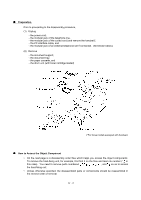
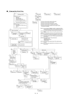
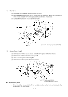
CHAPTER IV. DISASSEMBLY/REASSEMBLY AND LUBRICATION CONTENTS 1. DISASSEMBLY/REASSEMBLY IV-1 n Safety Precautions IV-1 n Preparation...IV-2 n How to Access the Object Component IV-2 n Disassembly Order Flow IV-3 1.1 Rear Cover ...IV-4 1.2 Access Plates R and F IV-4 1.3 Control Panel ASSY IV-5 1.4 Panel Rear Cover and Control Panel IV-6 1.5 Document Feed Roller ASSY, Document Ejection Roller ASSY, and Pinch Rollers IV-9 1.6 CIS Unit ...IV-10 1.7 Scanner Frame ASSY (Scanner Motor, Scanner Drive Unit, Document Take-in Roller, Separation Roller, Pressure Rollers, and Control Panel Locks IV-11 1.8 Top Cover (Exit Roller, Speaker, and Document Guides IV-15 1.9 Handset Mount and Hook Switch PCB (for models equipped with a handset) Side Cover (for models without handset IV-21 1.10 Paper Sub Tray IV-23 1.11 VC Cover, VC Bracket, and VC Connector PCB (for models supporting video capture IV-24 1.12 Front Cover Front Sub Cover (for models not supporting video capture IV-25 1.13 Outer Chute and Paper Pinch Rollers IV-26 1.14 Main Cover ...IV-27 1.15 Switch Cover ...IV-28 1.16 Laser Unit ...IV-29 1.17 Heat-fixing Unit and FU Lamp IV-30 [Disassembling the heat-fixing unit IV-32 1.18 Fan ...IV-44 1.19 Drive Gear ASSY and Main Motor ASSY IV-46 1.20 NCU Shield and NCU PCB IV-48 1.21 Bottom Plate, Main PCB and Bottom Insulation Film IV-50 1.22 Low-voltage Power Supply PCB and Power Inlet IV-54 i

  • 1
  • 2
  • 3
  • 4
  • 5
  • 6
  • 7
  • 8
  • 9
  • 10
  • 11
  • 12
  • 13
  • 14
  • 15
  • 16
  • 17
  • 18
  • 19
  • 20
  • 21
  • 22
  • 23
  • 24
  • 25
  • 26
  • 27
  • 28
  • 29
  • 30
  • 31
  • 32
  • 33
  • 34
  • 35
  • 36
  • 37
  • 38
  • 39
  • 40
  • 41
  • 42
  • 43
  • 44
  • 45
  • 46
  • 47
  • 48
  • 49
  • 50
  • 51
  • 52
  • 53
  • 54
  • 55
  • 56
  • 57
  • 58
  • 59
  • 60
  • 61
  • 62
  • 63
  • 64
  • 65
  • 66
  • 67
  • 68
  • 69
  • 70
  • 71
  • 72
  • 73
  • 74
  • 75
  • 76
  • 77
  • 78
  • 79
  • 80
  • 81
  • 82
  • 83
  • 84
  • 85
  • 86
  • 87
  • 88
  • 89
  • 90
  • 91
  • 92
  • 93
  • 94
  • 95
  • 96
  • 97
  • 98
  • 99
  • 100
  • 101
  • 102
  • 103
  • 104
  • 105
  • 106
  • 107
  • 108
  • 109
  • 110
  • 111
  • 112
  • 113
  • 114
  • 115
  • 116
  • 117
  • 118
  • 119
  • 120
  • 121
  • 122
  • 123
  • 124
  • 125
  • 126
  • 127
  • 128
  • 129
  • 130
  • 131
  • 132
  • 133
  • 134
  • 135
  • 136
  • 137
  • 138
  • 139
  • 140
  • 141
  • 142
  • 143
  • 144
  • 145
  • 146
  • 147
  • 148
  • 149
  • 150
  • 151
  • 152
  • 153
  • 154
  • 155
  • 156
  • 157
  • 158
  • 159
  • 160
  • 161
  • 162
  • 163
  • 164
  • 165
  • 166
  • 167
  • 168
  • 169
  • 170
  • 171
  • 172
  • 173
  • 174
  • 175
  • 176
  • 177
  • 178
  • 179
  • 180
  • 181
  • 182
  • 183
  • 184
  • 185
  • 186
  • 187
  • 188
  • 189
  • 190
  • 191
  • 192
  • 193
  • 194
  • 195
  • 196
  • 197
  • 198
  • 199
  • 200
  • 201
  • 202
  • 203
  • 204
  • 205
  • 206
  • 207
  • 208
  • 209
  • 210
  • 211
  • 212
  • 213
  • 214
  • 215
  • 216
  • 217
  • 218
  • 219
  • 220
  • 221
  • 222
  • 223
  • 224
  • 225
  • 226
  • 227
  • 228
  • 229
  • 230
  • 231
  • 232
  • 233
  • 234
  • 235
  • 236
  • 237
  • 238
  • 239

i
CHAPTER
IV
.
DISASSEMBLY/REASSEMBLY AND
LUBRICATION
CONTENTS
1.
DISASSEMBLY/REASSEMBLY
...............................................................................
IV
-1
n
Safety Precautions
..................................................................................................
IV
-1
n
Preparation
..............................................................................................................
IV
-2
n
How to Access the Object Component
...................................................................
IV
-2
n
Disassembly Order Flow
.........................................................................................
IV
-3
1.1
Rear Cover
.........................................................................................................
IV
-4
1.2
Access Plates R and F
.......................................................................................
IV
-4
1.3
Control Panel ASSY
...........................................................................................
IV
-5
1.4
Panel Rear Cover and Control Panel
.................................................................
IV
-6
1.5
Document Feed Roller ASSY, Document Ejection Roller ASSY,
and Pinch Rollers
...............................................................................................
IV
-9
1.6
CIS Unit
..............................................................................................................
IV
-10
1.7
Scanner Frame ASSY (Scanner Motor, Scanner Drive Unit,
Document Take-in Roller, Separation Roller, Pressure Rollers,
and Control Panel Locks)
...................................................................................
IV
-11
1.8
Top Cover (Exit Roller, Speaker, and Document Guides)
..................................
IV
-15
1.9
Handset Mount and Hook Switch PCB
(for models equipped with a handset)
Side Cover
(for models without handset)
...............................................................
IV
-21
1.10
Paper Sub Tray
..................................................................................................
IV
-23
1.11
VC Cover, VC Bracket, and VC Connector PCB
(for models supporting video capture)
.....................................................................
IV
-24
1.12
Front Cover
Front Sub Cover
(for models not supporting video capture)
....................................
IV
-25
1.13
Outer Chute and Paper Pinch Rollers
................................................................
IV
-26
1.14
Main Cover
.........................................................................................................
IV
-27
1.15
Switch Cover
......................................................................................................
IV
-28
1.16
Laser Unit
...........................................................................................................
IV
-29
1.17
Heat-fixing Unit and FU Lamp
............................................................................
IV
-30
[Disassembling the heat-fixing unit]
....................................................................
IV
-32
1.18
Fan
.....................................................................................................................
IV
-44
1.19
Drive Gear ASSY and Main Motor ASSY
...........................................................
IV
-46
1.20
NCU Shield and NCU PCB
.................................................................................
IV
-48
1.21
Bottom Plate, Main PCB and Bottom Insulation Film
.........................................
IV
-50
1.22
Low-voltage Power Supply PCB and Power Inlet
...............................................
IV
-54