Brother International MFC 8500 Service Manual - Page 126
Receiver Volume Adjustment (applicable to the American version only)
 |
UPC - 012502603832
View all Brother International MFC 8500 manuals
Add to My Manuals
Save this manual to your list of manuals |
Page 126 highlights
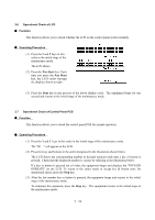
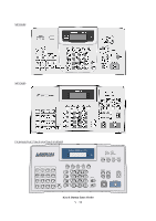
3.8 Receiver Volume Adjustment (applicable to the American version only) n Function The HIGH level of the handset receiver's volume will be influenced by the characteristics of the FET on the main PCB, so it requires fine adjustment according to the procedure given below. n Operating Procedure (1) Connect the telephone line cord to the modular jack of the facsimile equipment and the telephone wall socket. (2) Pick up the handset and listen to the dial tone. If the receiver volume is not appropriate, proceed to the following steps: (3) Press the 1 and 6 keys in this order in the initial stage of the maintenance mode. The LCD shows the current receiver volume (default: HIGH). (4) If the current receiver volume is not HIGH, use the Volume keys to choose HIGH. (5) Press the Fax Start key. The equipment enters the receiver volume adjustment mode and shows the PWM duty ratio at the right end of the LCD. (6) Adjust the receiver volume by using the 1, 3, 4, or 6 key. 1 key: Decrease 10H 3 key: Increase 10 H 4 key: Decrease 1H 6 key: Increase 1H (7) To escape from the receiver volume adjustment mode, press the Set key. The LCD shows the "PWM SETTING." One second later, the LCD returns to the screen shown in step (3). (8) To return the equipment to the initial stage of the maintenance mode, press the Stop key. V - 14
-
 1
1 -
2
-
3
-
4
-
5
-
6
-
7
-
8
-
9
-
10
-
11
-
12
-
13
-
14
-
15
-
16
-
17
-
18
-
19
-
20
-
21
-
22
-
23
-
24
-
25
-
26
-
27
-
28
-
29
-
30
-
31
-
32
-
33
-
34
-
35
-
36
-
37
-
38
-
39
-
40
-
41
-
42
-
43
-
44
-
45
-
46
-
47
-
48
-
49
-
50
-
51
-
52
-
53
-
54
-
55
-
56
-
57
-
58
-
59
-
60
-
61
-
62
-
63
-
64
-
65
-
66
-
67
-
68
-
69
-
70
-
71
-
72
-
73
-
74
-
75
-
76
-
77
-
78
-
79
-
80
-
81
-
82
-
83
-
84
-
85
-
86
-
87
-
88
-
89
-
90
-
91
-
92
-
93
-
94
-
95
-
96
-
97
-
98
-
99
-
100
-
101
-
102
-
103
-
104
-
105
-
106
-
107
-
108
-
109
-
110
-
111
-
112
-
113
-
114
-
115
-
116
-
117
-
118
-
119
-
120
-
 121
121 -
 122
122 -
 123
123 -
 124
124 -
 125
125 -
 126
126 -
 127
127 -
 128
128 -
 129
129 -
 130
130 -
 131
131 -
132
-
133
-
134
-
135
-
136
-
137
-
138
-
139
-
140
-
141
-
142
-
143
-
144
-
145
-
146
-
147
-
148
-
149
-
150
-
151
-
152
-
153
-
154
-
155
-
156
-
157
-
158
-
159
-
160
-
161
-
162
-
163
-
164
-
165
-
166
-
167
-
168
-
169
-
170
-
171
-
172
-
173
-
174
-
175
-
176
-
177
-
178
-
179
-
180
-
181
-
182
-
183
-
184
-
185
-
186
-
187
-
188
-
189
-
190
-
191
-
192
-
193
-
194
-
195
-
196
-
197
-
198
-
199
-
200
-
201
-
202
-
203
-
204
-
205
-
206
-
207
-
208
-
209
-
210
-
211
-
212
-
213
-
214
-
215
-
216
-
217
-
218
-
219
-
220
-
221
-
222
-
223
-
224
-
225
-
226
-
227
-
228
-
229
-
230
-
231
-
232
-
233
-
234
-
235
-
236
-
237
-
238
-
239
 |
 |