Brother International MFC 8500 Service Manual - Page 92
Taptite cup S M3x6, Taptite, bind B M4x12, Screw, pan washer M3.5x6
 |
UPC - 012502603832
View all Brother International MFC 8500 manuals
Add to My Manuals
Save this manual to your list of manuals |
Page 92 highlights
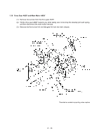
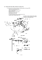
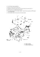
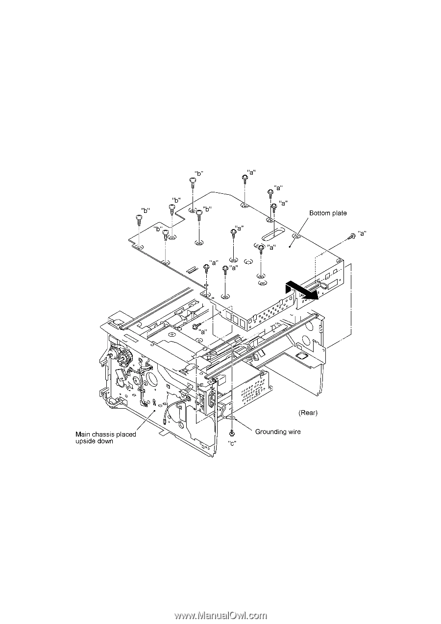
(2) Turn the main chassis upside down. (3) Remove 14 screws (nine "a" and five "b"). (4) Slightly lift up the bottom plate and pull it to the rear until you can remove screw "c." (5) Remove screw "c" to release the grounding wire. (6) For models available with a 2nd paper cassette: Unhook the 2nd cassette relay PCB bracket from the bottom plate. (7) Pull the bottom plate to the rear and out of the main chassis. "a": Taptite cup S M3x6 "b": Taptite, bind B M4x12 "c": Screw, pan (washer) M3.5x6 IV - 51
-
 1
1 -
2
-
3
-
4
-
5
-
6
-
7
-
8
-
9
-
10
-
11
-
12
-
13
-
14
-
15
-
16
-
17
-
18
-
19
-
20
-
21
-
22
-
23
-
24
-
25
-
26
-
27
-
28
-
29
-
30
-
31
-
32
-
33
-
34
-
35
-
36
-
37
-
38
-
39
-
40
-
41
-
42
-
43
-
44
-
45
-
46
-
47
-
48
-
49
-
50
-
51
-
52
-
53
-
54
-
55
-
56
-
57
-
58
-
59
-
60
-
61
-
62
-
63
-
64
-
65
-
66
-
67
-
68
-
69
-
70
-
71
-
72
-
73
-
74
-
75
-
76
-
77
-
78
-
79
-
80
-
81
-
82
-
83
-
84
-
85
-
86
-
 87
87 -
 88
88 -
 89
89 -
 90
90 -
 91
91 -
 92
92 -
 93
93 -
 94
94 -
 95
95 -
 96
96 -
 97
97 -
98
-
99
-
100
-
101
-
102
-
103
-
104
-
105
-
106
-
107
-
108
-
109
-
110
-
111
-
112
-
113
-
114
-
115
-
116
-
117
-
118
-
119
-
120
-
121
-
122
-
123
-
124
-
125
-
126
-
127
-
128
-
129
-
130
-
131
-
132
-
133
-
134
-
135
-
136
-
137
-
138
-
139
-
140
-
141
-
142
-
143
-
144
-
145
-
146
-
147
-
148
-
149
-
150
-
151
-
152
-
153
-
154
-
155
-
156
-
157
-
158
-
159
-
160
-
161
-
162
-
163
-
164
-
165
-
166
-
167
-
168
-
169
-
170
-
171
-
172
-
173
-
174
-
175
-
176
-
177
-
178
-
179
-
180
-
181
-
182
-
183
-
184
-
185
-
186
-
187
-
188
-
189
-
190
-
191
-
192
-
193
-
194
-
195
-
196
-
197
-
198
-
199
-
200
-
201
-
202
-
203
-
204
-
205
-
206
-
207
-
208
-
209
-
210
-
211
-
212
-
213
-
214
-
215
-
216
-
217
-
218
-
219
-
220
-
221
-
222
-
223
-
224
-
225
-
226
-
227
-
228
-
229
-
230
-
231
-
232
-
233
-
234
-
235
-
236
-
237
-
238
-
239
 |
 |
IV
- 51
(2)
Turn the main chassis upside down.
(3)
Remove 14 screws (nine "a" and five "b").
(4)
Slightly lift up the bottom plate and pull it to the rear until you can remove screw "c."
(5)
Remove screw "c" to release the grounding wire.
(6)
For models available with a 2nd paper cassette:
Unhook the 2nd cassette relay PCB bracket
from the bottom plate.
(7)
Pull the bottom plate to the rear and out of the main chassis.
"a":
Taptite cup S M3x6
"b":
Taptite, bind B M4x12
"c":
Screw, pan (washer) M3.5x6