D-Link DGS-3120-24TC Product Manual - Page 140
L3 Features, IPv4 Default Route Settings (SI Mode Only)
 |
View all D-Link DGS-3120-24TC manuals
Add to My Manuals
Save this manual to your list of manuals |
Page 140 highlights
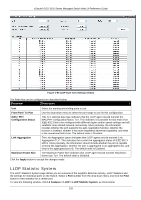
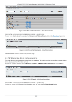
xStack® DGS-3120 Series Managed Switch Web UI Reference Guide Chapter 5 L3 Features IPv4 Default Route Settings (SI Mode Only) IPv4 Static/Default Route Settings (EI Mode Only) IPv4 Route Table IPv6 Static/Default Route Settings (EI Mode Only) IP Forwarding Table IPv4 Default Route Settings (SI Mode Only) Entries into the Switch's forwarding table can be made using both an IP address subnet mask and a gateway. To view the following window, click L3 Features > IPv4 Default Route Settings, as show below: Figure 5-1 IPv4 Default Route Settings window The fields that can be configured are described below: Parameter Description Gateway This field allows the entry of a Gateway IP Address to be applied to the corresponding gateway of the IP address. Metric Represents the metric value of the IP interface entered into the table. This field may read a number between 1 and 65535. Backup State Specifies the backup state of the default route created. Option to choose from are Primary and Backup. Click the Apply button to accept the changes made. IPv4 Static/Default Route Settings (EI Mode Only) The Switch supports static routing for IPv4 formatted addressing. Users can create up to 512 static route entries for IPv4. For IPv4 static routes, once a static route has been set, the Switch will send an ARP request packet to the next hop router that has been set by the user. Once an ARP response has been retrieved by the switch from that next hop, the route becomes enabled. However, if the ARP entry already exists, an ARP response will not be sent. The Switch also supports a floating static route, which means that the user may create an alternative static route to a different next hop. This secondary next hop device route is considered as a backup static route for when the primary static route is down. If the primary route is lost, the backup route will uplink and its status will become Active. Entries into the Switch's forwarding table can be made using both an IP address subnet mask and a gateway. To view the following window, click L3 Features > IPv4 Static/Default Route Settings, as show below: 132
-
 1
1 -
2
-
3
-
4
-
5
-
6
-
7
-
8
-
9
-
10
-
11
-
12
-
13
-
14
-
15
-
16
-
17
-
18
-
19
-
20
-
21
-
22
-
23
-
24
-
25
-
26
-
27
-
28
-
29
-
30
-
31
-
32
-
33
-
34
-
35
-
36
-
37
-
38
-
39
-
40
-
41
-
42
-
43
-
44
-
45
-
46
-
47
-
48
-
49
-
50
-
51
-
52
-
53
-
54
-
55
-
56
-
57
-
58
-
59
-
60
-
61
-
62
-
63
-
64
-
65
-
66
-
67
-
68
-
69
-
70
-
71
-
72
-
73
-
74
-
75
-
76
-
77
-
78
-
79
-
80
-
81
-
82
-
83
-
84
-
85
-
86
-
87
-
88
-
89
-
90
-
91
-
92
-
93
-
94
-
95
-
96
-
97
-
98
-
99
-
100
-
101
-
102
-
103
-
104
-
105
-
106
-
107
-
108
-
109
-
110
-
111
-
112
-
113
-
114
-
115
-
116
-
117
-
118
-
119
-
120
-
121
-
122
-
123
-
124
-
125
-
126
-
127
-
128
-
129
-
130
-
131
-
132
-
133
-
134
-
 135
135 -
 136
136 -
 137
137 -
 138
138 -
 139
139 -
 140
140 -
 141
141 -
 142
142 -
 143
143 -
 144
144 -
 145
145 -
146
-
147
-
148
-
149
-
150
-
151
-
152
-
153
-
154
-
155
-
156
-
157
-
158
-
159
-
160
-
161
-
162
-
163
-
164
-
165
-
166
-
167
-
168
-
169
-
170
-
171
-
172
-
173
-
174
-
175
-
176
-
177
-
178
-
179
-
180
-
181
-
182
-
183
-
184
-
185
-
186
-
187
-
188
-
189
-
190
-
191
-
192
-
193
-
194
-
195
-
196
-
197
-
198
-
199
-
200
-
201
-
202
-
203
-
204
-
205
-
206
-
207
-
208
-
209
-
210
-
211
-
212
-
213
-
214
-
215
-
216
-
217
-
218
-
219
-
220
-
221
-
222
-
223
-
224
-
225
-
226
-
227
-
228
-
229
-
230
-
231
-
232
-
233
-
234
-
235
-
236
-
237
-
238
-
239
-
240
-
241
-
242
-
243
-
244
-
245
-
246
-
247
-
248
-
249
-
250
-
251
-
252
-
253
-
254
-
255
-
256
-
257
-
258
-
259
-
260
-
261
-
262
-
263
-
264
-
265
-
266
-
267
-
268
-
269
-
270
-
271
-
272
-
273
-
274
-
275
-
276
-
277
-
278
-
279
-
280
-
281
-
282
-
283
-
284
-
285
-
286
-
287
-
288
-
289
-
290
-
291
-
292
-
293
-
294
-
295
-
296
-
297
-
298
-
299
-
300
-
301
-
302
-
303
-
304
-
305
-
306
-
307
-
308
-
309
-
310
-
311
-
312
-
313
-
314
-
315
-
316
-
317
-
318
-
319
-
320
-
321
-
322
-
323
-
324
-
325
-
326
-
327
-
328
-
329
-
330
-
331
-
332
-
333
-
334
-
335
-
336
-
337
-
338
-
339
 |
 |
