D-Link DGS-3120-24TC Product Manual - Page 165
Adding an IPv6 ACL Profile, Time Range Name
 |
View all D-Link DGS-3120-24TC manuals
Add to My Manuals
Save this manual to your list of manuals |
Page 165 highlights
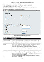
xStack® DGS-3120 Series Managed Switch Web UI Reference Guide defined in the config mirror port command. Port Mirroring must be enabled and a target port must be set. Priority (0-7) Tick the corresponding check box if you want to re-write the 802.1p default priority of a packet to the value entered in the Priority field, which meets the criteria specified previously in this command, before forwarding it on to the specified CoS queue. Otherwise, a packet will have its incoming 802.1p user priority re-written to its original value before being forwarded by the Switch. For more information on priority queues, CoS queues and mapping for 802.1p, see the QoS section of this manual. Replace Priority Tick this check box to replace the Priority value in the adjacent field. Replace DSCP (063) Select this option to instruct the Switch to replace the DSCP value (in a packet that meets the selected criteria) with the value entered in the adjacent field. When an ACL rule is added to change both the priority and DSCP of an IPv4 packet, only one of them can be modified due to a chip limitation. Currently the priority is changed when both the priority and DSCP are set to be modified. Replace ToS Precedence (0-7) Specify that the IP precedence of the outgoing packet is changed with the new value. If used without an action priority, the packet is sent to the default TC. Time Range Name Tick the check box and enter the name of the Time Range settings that has been previously configured in the Time Range Settings window. This will set specific times when this access rule will be implemented on the Switch. Counter Here the user can select the counter. By checking the counter, the administrator can see how many times that the rule was hit. Ports When a range of ports is to be configured, the Auto Assign check box MUST be ticked in the Access ID field of this window. If not, the user will be presented with an error message and the access rule will not be configured. Ticking the All Ports check box will denote all ports on the Switch. VLAN Name Specify the VLAN name to apply to the access rule. VLAN ID Specify the VLAN ID to apply to the access rule. Click the Apply button to accept the changes made. Click the
-
 1
1 -
2
-
3
-
4
-
5
-
6
-
7
-
8
-
9
-
10
-
11
-
12
-
13
-
14
-
15
-
16
-
17
-
18
-
19
-
20
-
21
-
22
-
23
-
24
-
25
-
26
-
27
-
28
-
29
-
30
-
31
-
32
-
33
-
34
-
35
-
36
-
37
-
38
-
39
-
40
-
41
-
42
-
43
-
44
-
45
-
46
-
47
-
48
-
49
-
50
-
51
-
52
-
53
-
54
-
55
-
56
-
57
-
58
-
59
-
60
-
61
-
62
-
63
-
64
-
65
-
66
-
67
-
68
-
69
-
70
-
71
-
72
-
73
-
74
-
75
-
76
-
77
-
78
-
79
-
80
-
81
-
82
-
83
-
84
-
85
-
86
-
87
-
88
-
89
-
90
-
91
-
92
-
93
-
94
-
95
-
96
-
97
-
98
-
99
-
100
-
101
-
102
-
103
-
104
-
105
-
106
-
107
-
108
-
109
-
110
-
111
-
112
-
113
-
114
-
115
-
116
-
117
-
118
-
119
-
120
-
121
-
122
-
123
-
124
-
125
-
126
-
127
-
128
-
129
-
130
-
131
-
132
-
133
-
134
-
135
-
136
-
137
-
138
-
139
-
140
-
141
-
142
-
143
-
144
-
145
-
146
-
147
-
148
-
149
-
150
-
151
-
152
-
153
-
154
-
155
-
156
-
157
-
158
-
159
-
 160
160 -
 161
161 -
 162
162 -
 163
163 -
 164
164 -
 165
165 -
 166
166 -
 167
167 -
 168
168 -
 169
169 -
 170
170 -
171
-
172
-
173
-
174
-
175
-
176
-
177
-
178
-
179
-
180
-
181
-
182
-
183
-
184
-
185
-
186
-
187
-
188
-
189
-
190
-
191
-
192
-
193
-
194
-
195
-
196
-
197
-
198
-
199
-
200
-
201
-
202
-
203
-
204
-
205
-
206
-
207
-
208
-
209
-
210
-
211
-
212
-
213
-
214
-
215
-
216
-
217
-
218
-
219
-
220
-
221
-
222
-
223
-
224
-
225
-
226
-
227
-
228
-
229
-
230
-
231
-
232
-
233
-
234
-
235
-
236
-
237
-
238
-
239
-
240
-
241
-
242
-
243
-
244
-
245
-
246
-
247
-
248
-
249
-
250
-
251
-
252
-
253
-
254
-
255
-
256
-
257
-
258
-
259
-
260
-
261
-
262
-
263
-
264
-
265
-
266
-
267
-
268
-
269
-
270
-
271
-
272
-
273
-
274
-
275
-
276
-
277
-
278
-
279
-
280
-
281
-
282
-
283
-
284
-
285
-
286
-
287
-
288
-
289
-
290
-
291
-
292
-
293
-
294
-
295
-
296
-
297
-
298
-
299
-
300
-
301
-
302
-
303
-
304
-
305
-
306
-
307
-
308
-
309
-
310
-
311
-
312
-
313
-
314
-
315
-
316
-
317
-
318
-
319
-
320
-
321
-
322
-
323
-
324
-
325
-
326
-
327
-
328
-
329
-
330
-
331
-
332
-
333
-
334
-
335
-
336
-
337
-
338
-
339
 |
 |
