D-Link DGS-3120-24TC Product Manual - Page 82
Service Provider VLAN IDs. These VLANs are marked by a TPID Tagged Protocol ID
 |
View all D-Link DGS-3120-24TC manuals
Add to My Manuals
Save this manual to your list of manuals |
Page 82 highlights
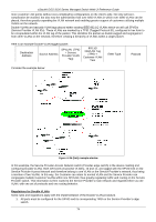
xStack® DGS-3120 Series Managed Switch Web UI Reference Guide more customer LAN points without over-complicating configurations on the client's side. Not only will overcomplication be avoided, but also now the administrator has over 4000 VLANs in which over 4000 VLANs can be placed, therefore greatly expanding the VLAN network and enabling greater support of customers utilizing multiple VLANs on the network. Double VLANs are basically VLAN tags placed within existing IEEE 802.1Q VLANs which we will call SPVIDs (Service Provider VLAN IDs). These VLANs are marked by a TPID (Tagged Protocol ID), configured in hex form to be encapsulated within the VLAN tag of the packet. This identifies the packet as double-tagged and segregates it from other VLANs on the network, therefore creating a hierarchy of VLANs within a single packet. Here is an example Double VLAN tagged packet. Destination Address Source Address SPVLAN (TPID + Service Provider VLAN Tag) 802.1Q CEVLAN Tag (TPID + Customer VLAN Tag) Ether Type Payload Consider the example below: Figure 4-25 QinQ example window In this example, the Service Provider Access Network switch (Provider edge switch) is the device creating and configuring Double VLANs. Both CEVLANs (Customer VLANs), 10 and 11, are tagged with the SPVID 100 on the Service Provider Access Network and therefore belong to one VLAN on the Service Provider's network, thus being a member of two VLANs. In this way, the Customer can retain its normal VLAN and the Service Provider can congregate multiple Customer VLANs within one SPVLAN, thus greatly regulating traffic and routing on the Service Provider switch. This information is then routed to the Service Provider's main network and regarded there as one VLAN, with one set of protocols and one routing behavior. Regulations for Double VLANs Some rules and regulations apply with the implementation of the Double VLAN procedure. 1. All ports must be configured for the SPVID and its corresponding TPID on the Service Provider's edge switch. 74
-
 1
1 -
2
-
3
-
4
-
5
-
6
-
7
-
8
-
9
-
10
-
11
-
12
-
13
-
14
-
15
-
16
-
17
-
18
-
19
-
20
-
21
-
22
-
23
-
24
-
25
-
26
-
27
-
28
-
29
-
30
-
31
-
32
-
33
-
34
-
35
-
36
-
37
-
38
-
39
-
40
-
41
-
42
-
43
-
44
-
45
-
46
-
47
-
48
-
49
-
50
-
51
-
52
-
53
-
54
-
55
-
56
-
57
-
58
-
59
-
60
-
61
-
62
-
63
-
64
-
65
-
66
-
67
-
68
-
69
-
70
-
71
-
72
-
73
-
74
-
75
-
76
-
 77
77 -
 78
78 -
 79
79 -
 80
80 -
 81
81 -
 82
82 -
 83
83 -
 84
84 -
 85
85 -
 86
86 -
 87
87 -
88
-
89
-
90
-
91
-
92
-
93
-
94
-
95
-
96
-
97
-
98
-
99
-
100
-
101
-
102
-
103
-
104
-
105
-
106
-
107
-
108
-
109
-
110
-
111
-
112
-
113
-
114
-
115
-
116
-
117
-
118
-
119
-
120
-
121
-
122
-
123
-
124
-
125
-
126
-
127
-
128
-
129
-
130
-
131
-
132
-
133
-
134
-
135
-
136
-
137
-
138
-
139
-
140
-
141
-
142
-
143
-
144
-
145
-
146
-
147
-
148
-
149
-
150
-
151
-
152
-
153
-
154
-
155
-
156
-
157
-
158
-
159
-
160
-
161
-
162
-
163
-
164
-
165
-
166
-
167
-
168
-
169
-
170
-
171
-
172
-
173
-
174
-
175
-
176
-
177
-
178
-
179
-
180
-
181
-
182
-
183
-
184
-
185
-
186
-
187
-
188
-
189
-
190
-
191
-
192
-
193
-
194
-
195
-
196
-
197
-
198
-
199
-
200
-
201
-
202
-
203
-
204
-
205
-
206
-
207
-
208
-
209
-
210
-
211
-
212
-
213
-
214
-
215
-
216
-
217
-
218
-
219
-
220
-
221
-
222
-
223
-
224
-
225
-
226
-
227
-
228
-
229
-
230
-
231
-
232
-
233
-
234
-
235
-
236
-
237
-
238
-
239
-
240
-
241
-
242
-
243
-
244
-
245
-
246
-
247
-
248
-
249
-
250
-
251
-
252
-
253
-
254
-
255
-
256
-
257
-
258
-
259
-
260
-
261
-
262
-
263
-
264
-
265
-
266
-
267
-
268
-
269
-
270
-
271
-
272
-
273
-
274
-
275
-
276
-
277
-
278
-
279
-
280
-
281
-
282
-
283
-
284
-
285
-
286
-
287
-
288
-
289
-
290
-
291
-
292
-
293
-
294
-
295
-
296
-
297
-
298
-
299
-
300
-
301
-
302
-
303
-
304
-
305
-
306
-
307
-
308
-
309
-
310
-
311
-
312
-
313
-
314
-
315
-
316
-
317
-
318
-
319
-
320
-
321
-
322
-
323
-
324
-
325
-
326
-
327
-
328
-
329
-
330
-
331
-
332
-
333
-
334
-
335
-
336
-
337
-
338
-
339
 |
 |
