D-Link DGS-3120-24TC Product Manual - Page 180
Add Rule, <<Back, Show Details, Delete Rules, Access ID 1-100, Action, VLAN Name
 |
View all D-Link DGS-3120-24TC manuals
Add to My Manuals
Save this manual to your list of manuals |
Page 180 highlights
xStack® DGS-3120 Series Managed Switch Web UI Reference Guide Figure 7-31 CPU Access Rule List (IPv4 ACL) Click the Add Rule button to create a new CPU ACL rule in this profile. Click the
-
 1
1 -
2
-
3
-
4
-
5
-
6
-
7
-
8
-
9
-
10
-
11
-
12
-
13
-
14
-
15
-
16
-
17
-
18
-
19
-
20
-
21
-
22
-
23
-
24
-
25
-
26
-
27
-
28
-
29
-
30
-
31
-
32
-
33
-
34
-
35
-
36
-
37
-
38
-
39
-
40
-
41
-
42
-
43
-
44
-
45
-
46
-
47
-
48
-
49
-
50
-
51
-
52
-
53
-
54
-
55
-
56
-
57
-
58
-
59
-
60
-
61
-
62
-
63
-
64
-
65
-
66
-
67
-
68
-
69
-
70
-
71
-
72
-
73
-
74
-
75
-
76
-
77
-
78
-
79
-
80
-
81
-
82
-
83
-
84
-
85
-
86
-
87
-
88
-
89
-
90
-
91
-
92
-
93
-
94
-
95
-
96
-
97
-
98
-
99
-
100
-
101
-
102
-
103
-
104
-
105
-
106
-
107
-
108
-
109
-
110
-
111
-
112
-
113
-
114
-
115
-
116
-
117
-
118
-
119
-
120
-
121
-
122
-
123
-
124
-
125
-
126
-
127
-
128
-
129
-
130
-
131
-
132
-
133
-
134
-
135
-
136
-
137
-
138
-
139
-
140
-
141
-
142
-
143
-
144
-
145
-
146
-
147
-
148
-
149
-
150
-
151
-
152
-
153
-
154
-
155
-
156
-
157
-
158
-
159
-
160
-
161
-
162
-
163
-
164
-
165
-
166
-
167
-
168
-
169
-
170
-
171
-
172
-
173
-
174
-
 175
175 -
 176
176 -
 177
177 -
 178
178 -
 179
179 -
 180
180 -
 181
181 -
 182
182 -
 183
183 -
 184
184 -
 185
185 -
186
-
187
-
188
-
189
-
190
-
191
-
192
-
193
-
194
-
195
-
196
-
197
-
198
-
199
-
200
-
201
-
202
-
203
-
204
-
205
-
206
-
207
-
208
-
209
-
210
-
211
-
212
-
213
-
214
-
215
-
216
-
217
-
218
-
219
-
220
-
221
-
222
-
223
-
224
-
225
-
226
-
227
-
228
-
229
-
230
-
231
-
232
-
233
-
234
-
235
-
236
-
237
-
238
-
239
-
240
-
241
-
242
-
243
-
244
-
245
-
246
-
247
-
248
-
249
-
250
-
251
-
252
-
253
-
254
-
255
-
256
-
257
-
258
-
259
-
260
-
261
-
262
-
263
-
264
-
265
-
266
-
267
-
268
-
269
-
270
-
271
-
272
-
273
-
274
-
275
-
276
-
277
-
278
-
279
-
280
-
281
-
282
-
283
-
284
-
285
-
286
-
287
-
288
-
289
-
290
-
291
-
292
-
293
-
294
-
295
-
296
-
297
-
298
-
299
-
300
-
301
-
302
-
303
-
304
-
305
-
306
-
307
-
308
-
309
-
310
-
311
-
312
-
313
-
314
-
315
-
316
-
317
-
318
-
319
-
320
-
321
-
322
-
323
-
324
-
325
-
326
-
327
-
328
-
329
-
330
-
331
-
332
-
333
-
334
-
335
-
336
-
337
-
338
-
339
 |
 |

xStack® DGS-3120 Series Managed Switch Web UI Reference Guide
172
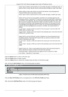
Figure 7–31 CPU Access Rule List (IPv4 ACL)
Click the
Add Rule
button to create a new CPU ACL rule in this profile.
Click the
<<Back
button to return to the previous page.
Click the
Show Details
button to view more information about the specific rule created.
Click the
Delete Rules
button to remove the specific entry.
Enter a page number and click the
Go
button to navigate to a specific page when multiple pages exist.
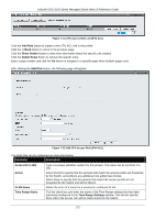
After clicking the
Add Rule
button, the following page will appear:
Figure 7–32 Add CPU Access Rule (IPv4 ACL)
The fields that can be configured are described below:
Parameter
Description
Access ID (1-100)
Type in a unique identifier number for this access. This value can be set from
1
to
100
.
Action
Select
Permit
to specify that the packets that match the access profile are forwarded
by the Switch, according to any additional rule added (see below).
Select
Deny
to specify that the packets that match the access profile are not
forwarded by the Switch and will be filtered.
VLAN Name
Allows the entry of a name for a previously configured VLAN.
Time Range Name
Tick the check box and enter the name of the Time Range settings that has been
previously configured in the
Time Range
Settings
window. This will set specific
times when this access rule will be implemented on the Switch.