Epson ActionLaser User Manual - Page 202
Signal, Description, Serial interface pin assignments, Technical Specifications
 |
View all Epson ActionLaser manuals
Add to My Manuals
Save this manual to your list of manuals |
Page 202 highlights
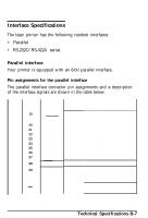
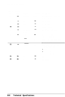
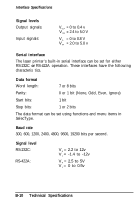
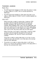
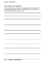
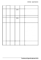
Inferface Specifications Serial interface pin assignments The serial interface connector pin assignments and a description of the interface signals are shown in the table below. The direction of signals is given relative to the printer. Signal Pin Signal 1 FG 2 TD 3 RD 4 RTS 5 CTS 6 DSR 7 SG 9 SD RS-232C RS-422A Direction * * * OUT * (RD-) IN invert * OUT * IN * IN * (SD-) invert OUT Description Frame ground. Safety ground line. Transmit data. This pin transmits serial data from the printer to the computer. Receive data. This pin transmits serial data from the computer to the printer. Request to send. This pin is HIGH when power is on. Clear to send. This pin indicates that the computer is ready to receive data from the printer. Data set ready. This pin indicates that the computer is ready to communicate. Signal ground. This pin provides a ground for all the signal lines. Send data. This pin sends serial data from the printer to the computer. Signal level is RS-422A. B-12 Technical Specifications
-
 1
1 -
2
-
3
-
4
-
5
-
6
-
7
-
8
-
9
-
10
-
11
-
12
-
13
-
14
-
15
-
16
-
17
-
18
-
19
-
20
-
21
-
22
-
23
-
24
-
25
-
26
-
27
-
28
-
29
-
30
-
31
-
32
-
33
-
34
-
35
-
36
-
37
-
38
-
39
-
40
-
41
-
42
-
43
-
44
-
45
-
46
-
47
-
48
-
49
-
50
-
51
-
52
-
53
-
54
-
55
-
56
-
57
-
58
-
59
-
60
-
61
-
62
-
63
-
64
-
65
-
66
-
67
-
68
-
69
-
70
-
71
-
72
-
73
-
74
-
75
-
76
-
77
-
78
-
79
-
80
-
81
-
82
-
83
-
84
-
85
-
86
-
87
-
88
-
89
-
90
-
91
-
92
-
93
-
94
-
95
-
96
-
97
-
98
-
99
-
100
-
101
-
102
-
103
-
104
-
105
-
106
-
107
-
108
-
109
-
110
-
111
-
112
-
113
-
114
-
115
-
116
-
117
-
118
-
119
-
120
-
121
-
122
-
123
-
124
-
125
-
126
-
127
-
128
-
129
-
130
-
131
-
132
-
133
-
134
-
135
-
136
-
137
-
138
-
139
-
140
-
141
-
142
-
143
-
144
-
145
-
146
-
147
-
148
-
149
-
150
-
151
-
152
-
153
-
154
-
155
-
156
-
157
-
158
-
159
-
160
-
161
-
162
-
163
-
164
-
165
-
166
-
167
-
168
-
169
-
170
-
171
-
172
-
173
-
174
-
175
-
176
-
177
-
178
-
179
-
180
-
181
-
182
-
183
-
184
-
185
-
186
-
187
-
188
-
189
-
190
-
191
-
192
-
193
-
194
-
195
-
196
-
 197
197 -
 198
198 -
 199
199 -
 200
200 -
 201
201 -
 202
202 -
 203
203 -
 204
204 -
 205
205 -
 206
206 -
 207
207 -
208
-
209
-
210
-
211
-
212
-
213
-
214
-
215
-
216
-
217
-
218
-
219
 |
 |