Epson ActionLaser User Manual - Page 52
Setting the DIP switches for the serial interface
 |
View all Epson ActionLaser manuals
Add to My Manuals
Save this manual to your list of manuals |
Page 52 highlights
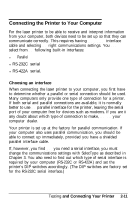
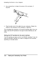
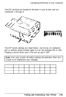
Connecting the Printer to Your Computer 3. Use a screwdriver to fasten the screws of the connector, if required. 4. Plug the other end of the cable into your computer. (Fasten the screws of the connector to the interface, if required.) This completes the connection of the serial interface cable. Now you need to set the DIP switches for the type of serial interface you are using. Setting the DIP switches for the serial interface The DIP switches are factory set for the RS-232C interface. If you are using the RS-422A interface, you need to change the DIP switches according to the table below. 2-14 Testing and Connecting Your Printer
-
 1
1 -
2
-
3
-
4
-
5
-
6
-
7
-
8
-
9
-
10
-
11
-
12
-
13
-
14
-
15
-
16
-
17
-
18
-
19
-
20
-
21
-
22
-
23
-
24
-
25
-
26
-
27
-
28
-
29
-
30
-
31
-
32
-
33
-
34
-
35
-
36
-
37
-
38
-
39
-
40
-
41
-
42
-
43
-
44
-
45
-
46
-
 47
47 -
 48
48 -
 49
49 -
 50
50 -
 51
51 -
 52
52 -
 53
53 -
 54
54 -
 55
55 -
 56
56 -
 57
57 -
58
-
59
-
60
-
61
-
62
-
63
-
64
-
65
-
66
-
67
-
68
-
69
-
70
-
71
-
72
-
73
-
74
-
75
-
76
-
77
-
78
-
79
-
80
-
81
-
82
-
83
-
84
-
85
-
86
-
87
-
88
-
89
-
90
-
91
-
92
-
93
-
94
-
95
-
96
-
97
-
98
-
99
-
100
-
101
-
102
-
103
-
104
-
105
-
106
-
107
-
108
-
109
-
110
-
111
-
112
-
113
-
114
-
115
-
116
-
117
-
118
-
119
-
120
-
121
-
122
-
123
-
124
-
125
-
126
-
127
-
128
-
129
-
130
-
131
-
132
-
133
-
134
-
135
-
136
-
137
-
138
-
139
-
140
-
141
-
142
-
143
-
144
-
145
-
146
-
147
-
148
-
149
-
150
-
151
-
152
-
153
-
154
-
155
-
156
-
157
-
158
-
159
-
160
-
161
-
162
-
163
-
164
-
165
-
166
-
167
-
168
-
169
-
170
-
171
-
172
-
173
-
174
-
175
-
176
-
177
-
178
-
179
-
180
-
181
-
182
-
183
-
184
-
185
-
186
-
187
-
188
-
189
-
190
-
191
-
192
-
193
-
194
-
195
-
196
-
197
-
198
-
199
-
200
-
201
-
202
-
203
-
204
-
205
-
206
-
207
-
208
-
209
-
210
-
211
-
212
-
213
-
214
-
215
-
216
-
217
-
218
-
219
 |
 |
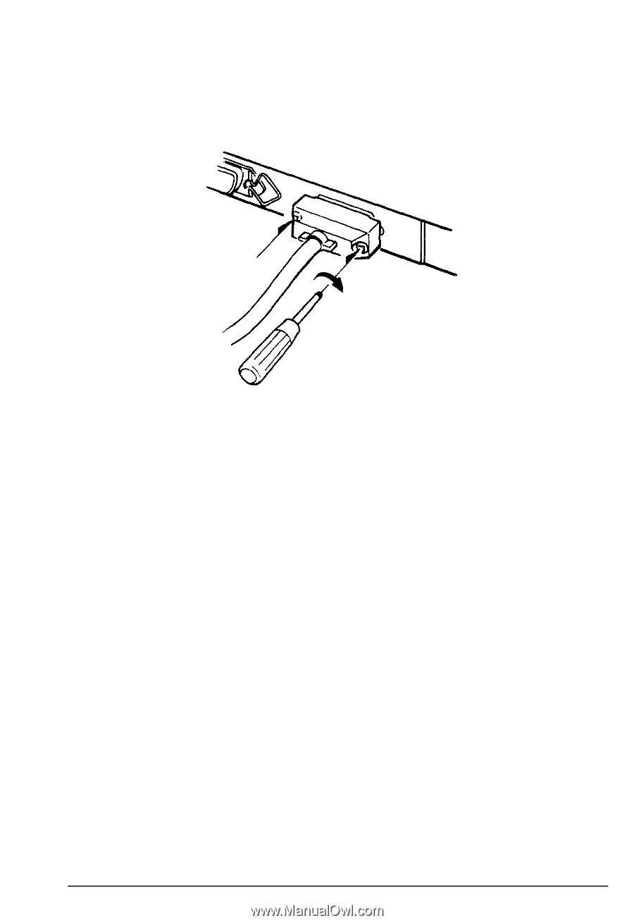
Connecting the Printer to Your Computer
3.
Use a screwdriver to fasten the screws of the connector, if
required.
4.
Plug the other end of the cable into your computer. (Fasten the
screws of the connector to the interface, if required.)
This completes the connection of the serial interface cable. Now you
need to set the DIP switches for the type of serial interface you are
using.
Setting the DIP switches for the serial interface
The DIP switches are factory set for the RS-232C interface. If you are
using the RS-422A interface, you need to change the DIP switches
according to the table below.
2-14
Testing and Connecting Your Printer