HP 6125G HP 6125G & 6125G/XG Blade Switches Security Configuration Gui - Page 278
Manual-mode MFF configuration example in a ring network, Network requirements, Configuration
 |
View all HP 6125G manuals
Add to My Manuals
Save this manual to your list of manuals |
Page 278 highlights
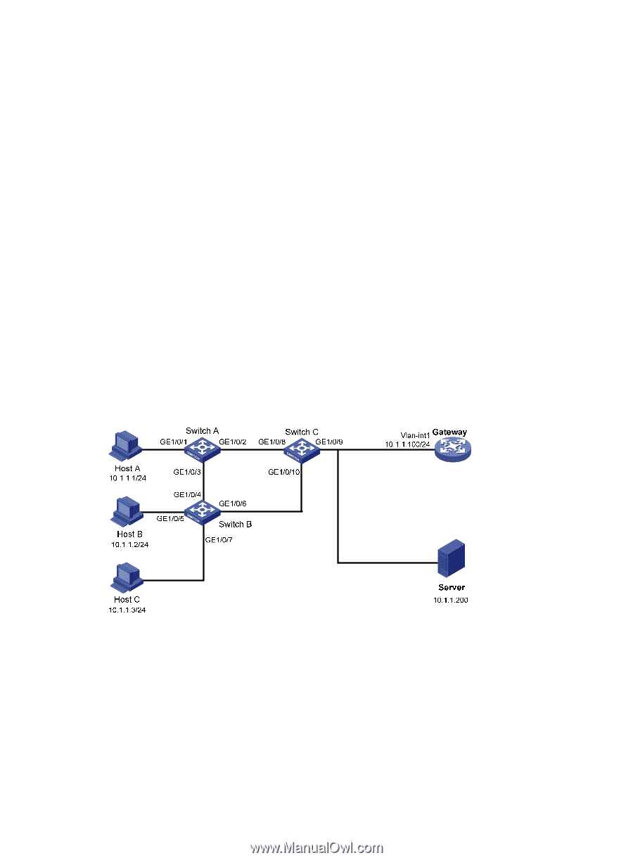
[SwitchA-GigabitEthernet1/0/2] mac-forced-forwarding network-port 4. Configure Switch B: # Configure manual-mode MFF. [SwitchB] vlan 100 [SwitchB-vlan-100] mac-forced-forwarding default-gateway 10.1.1.100 # Specify the IP address of the server. [SwitchB-vlan-100] mac-forced-forwarding server 10.1.1.200 # Enable ARP snooping. [SwitchB-vlan-100] arp-snooping enable [SwitchB-vlan-100] quit # Configure GigabitEthernet 1/0/6 as a network port. [SwitchB] interface gigabitethernet 1/0/6 [SwitchB-GigabitEthernet1/0/6] mac-forced-forwarding network-port Manual-mode MFF configuration example in a ring network Network requirements As shown in Figure 87, all the devices are in VLAN 100, and the switches form a ring. Host A, Host B, and Host C are configured with IP addresses manually. They are isolated at Layer 2, and can communicate with each other through the gateway. To ensure communication between hosts and the server, the IP address of the server is specified on the MFF devices manually. Figure 87 Network diagram Configuration procedure 1. Configure IP addresses of the hosts, as in shown in Figure 87. 2. Configure the IP address of VLAN-interface 1 on the gateway. system-view [Gateway] interface Vlan-interface 1 [Gateway-Vlan-interface1] ip address 10.1.1.100 24 3. Configure Switch A: # Enable STP. [SwitchA] stp enable 268
-
 1
1 -
2
-
3
-
4
-
5
-
6
-
7
-
8
-
9
-
10
-
11
-
12
-
13
-
14
-
15
-
16
-
17
-
18
-
19
-
20
-
21
-
22
-
23
-
24
-
25
-
26
-
27
-
28
-
29
-
30
-
31
-
32
-
33
-
34
-
35
-
36
-
37
-
38
-
39
-
40
-
41
-
42
-
43
-
44
-
45
-
46
-
47
-
48
-
49
-
50
-
51
-
52
-
53
-
54
-
55
-
56
-
57
-
58
-
59
-
60
-
61
-
62
-
63
-
64
-
65
-
66
-
67
-
68
-
69
-
70
-
71
-
72
-
73
-
74
-
75
-
76
-
77
-
78
-
79
-
80
-
81
-
82
-
83
-
84
-
85
-
86
-
87
-
88
-
89
-
90
-
91
-
92
-
93
-
94
-
95
-
96
-
97
-
98
-
99
-
100
-
101
-
102
-
103
-
104
-
105
-
106
-
107
-
108
-
109
-
110
-
111
-
112
-
113
-
114
-
115
-
116
-
117
-
118
-
119
-
120
-
121
-
122
-
123
-
124
-
125
-
126
-
127
-
128
-
129
-
130
-
131
-
132
-
133
-
134
-
135
-
136
-
137
-
138
-
139
-
140
-
141
-
142
-
143
-
144
-
145
-
146
-
147
-
148
-
149
-
150
-
151
-
152
-
153
-
154
-
155
-
156
-
157
-
158
-
159
-
160
-
161
-
162
-
163
-
164
-
165
-
166
-
167
-
168
-
169
-
170
-
171
-
172
-
173
-
174
-
175
-
176
-
177
-
178
-
179
-
180
-
181
-
182
-
183
-
184
-
185
-
186
-
187
-
188
-
189
-
190
-
191
-
192
-
193
-
194
-
195
-
196
-
197
-
198
-
199
-
200
-
201
-
202
-
203
-
204
-
205
-
206
-
207
-
208
-
209
-
210
-
211
-
212
-
213
-
214
-
215
-
216
-
217
-
218
-
219
-
220
-
221
-
222
-
223
-
224
-
225
-
226
-
227
-
228
-
229
-
230
-
231
-
232
-
233
-
234
-
235
-
236
-
237
-
238
-
239
-
240
-
241
-
242
-
243
-
244
-
245
-
246
-
247
-
248
-
249
-
250
-
251
-
252
-
253
-
254
-
255
-
256
-
257
-
258
-
259
-
260
-
261
-
262
-
263
-
264
-
265
-
266
-
267
-
268
-
269
-
270
-
271
-
272
-
 273
273 -
 274
274 -
 275
275 -
 276
276 -
 277
277 -
 278
278 -
 279
279 -
 280
280 -
 281
281 -
 282
282 -
 283
283 -
284
-
285
 |
 |