HP 6125G HP 6125G & 6125G/XG Blade Switches Security Configuration Gui - Page 36
Specifying the source IP address for outgoing RADIUS packets
 |
View all HP 6125G manuals
Add to My Manuals
Save this manual to your list of manuals |
Page 36 highlights
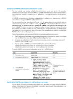
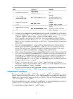
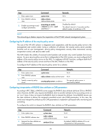
• If one server is in active state and all the others are in blocked state, the switch only tries to communicate with the server in active state, even if the server is unavailable. • After receiving an authentication/accounting response from a server, the switch changes the status of the server identified by the source IP address of the response to active if the current status of the server is blocked. The device does not change the status of an unreachable authentication or accounting server if the server quiet timer is set to 0. Instead, the device keeps the server status as active and sends authentication or accounting packets to another server in active state, so subsequent authentication or accounting packets can still be sent to that server. For more information about the server quiet timer, see "Setting timers for controlling communication with HWTACACS servers." By default, the switch sets the status of all RADIUS servers to active. In cases such as a server failure, you can change the status of the server to blocked to avoid communication with the server. To set the status of RADIUS servers in a RADIUS scheme: Step 1. Enter system view. 2. Enter RADIUS scheme view. 3. Set the RADIUS server status. Command system-view Remarks N/A radius scheme radius-scheme-name N/A • Set the status of the primary RADIUS authentication/authorization server: state primary authentication { active | block } • Set the status of the primary RADIUS accounting server: state primary accounting { active | block } Optional. • Set the status of a secondary RADIUS authentication/authorization server: state secondary authentication [ ip ipv4-address | ipv6 ipv6-address ] { active | By default, all servers in the RADIUS scheme are in active state. block } • Set the status of a secondary RADIUS accounting server: state secondary accounting [ ip ipv4-address | ipv6 ipv6-address ] { active | block } NOTE: • The server status set by the state command cannot be saved to the configuration file. After the switch restarts, the status of each server is restored to active. • To display the states of the servers, use the display radius scheme command. Specifying the source IP address for outgoing RADIUS packets The source IP address of RADIUS packets that a NAS sends must match the IP address of the NAS configured on the RADIUS server. A RADIUS server identifies a NAS by its IP address. Upon receiving a RADIUS packet, a RADIUS server checks whether the source IP address of the packet is the IP address of any managed NAS. If yes, the server processes the packet. If not, the server drops the packet. Usually, the source address of outgoing RADIUS packets can be the IP address of the NAS's any interface that can communicate with the RADIUS server. In some special scenarios, however, you must change the source IP address. For example, if a Network Address Translation (NAT) device is present 26
-
 1
1 -
2
-
3
-
4
-
5
-
6
-
7
-
8
-
9
-
10
-
11
-
12
-
13
-
14
-
15
-
16
-
17
-
18
-
19
-
20
-
21
-
22
-
23
-
24
-
25
-
26
-
27
-
28
-
29
-
30
-
 31
31 -
 32
32 -
 33
33 -
 34
34 -
 35
35 -
 36
36 -
 37
37 -
 38
38 -
 39
39 -
 40
40 -
 41
41 -
42
-
43
-
44
-
45
-
46
-
47
-
48
-
49
-
50
-
51
-
52
-
53
-
54
-
55
-
56
-
57
-
58
-
59
-
60
-
61
-
62
-
63
-
64
-
65
-
66
-
67
-
68
-
69
-
70
-
71
-
72
-
73
-
74
-
75
-
76
-
77
-
78
-
79
-
80
-
81
-
82
-
83
-
84
-
85
-
86
-
87
-
88
-
89
-
90
-
91
-
92
-
93
-
94
-
95
-
96
-
97
-
98
-
99
-
100
-
101
-
102
-
103
-
104
-
105
-
106
-
107
-
108
-
109
-
110
-
111
-
112
-
113
-
114
-
115
-
116
-
117
-
118
-
119
-
120
-
121
-
122
-
123
-
124
-
125
-
126
-
127
-
128
-
129
-
130
-
131
-
132
-
133
-
134
-
135
-
136
-
137
-
138
-
139
-
140
-
141
-
142
-
143
-
144
-
145
-
146
-
147
-
148
-
149
-
150
-
151
-
152
-
153
-
154
-
155
-
156
-
157
-
158
-
159
-
160
-
161
-
162
-
163
-
164
-
165
-
166
-
167
-
168
-
169
-
170
-
171
-
172
-
173
-
174
-
175
-
176
-
177
-
178
-
179
-
180
-
181
-
182
-
183
-
184
-
185
-
186
-
187
-
188
-
189
-
190
-
191
-
192
-
193
-
194
-
195
-
196
-
197
-
198
-
199
-
200
-
201
-
202
-
203
-
204
-
205
-
206
-
207
-
208
-
209
-
210
-
211
-
212
-
213
-
214
-
215
-
216
-
217
-
218
-
219
-
220
-
221
-
222
-
223
-
224
-
225
-
226
-
227
-
228
-
229
-
230
-
231
-
232
-
233
-
234
-
235
-
236
-
237
-
238
-
239
-
240
-
241
-
242
-
243
-
244
-
245
-
246
-
247
-
248
-
249
-
250
-
251
-
252
-
253
-
254
-
255
-
256
-
257
-
258
-
259
-
260
-
261
-
262
-
263
-
264
-
265
-
266
-
267
-
268
-
269
-
270
-
271
-
272
-
273
-
274
-
275
-
276
-
277
-
278
-
279
-
280
-
281
-
282
-
283
-
284
-
285
 |
 |