HP 6125G HP 6125G & 6125G/XG Blade Switches Security Configuration Gui - Page 62
Configuration prerequisites, Configuring the RADIUS server, Service, User Access Manager
 |
View all HP 6125G manuals
Add to My Manuals
Save this manual to your list of manuals |
Page 62 highlights
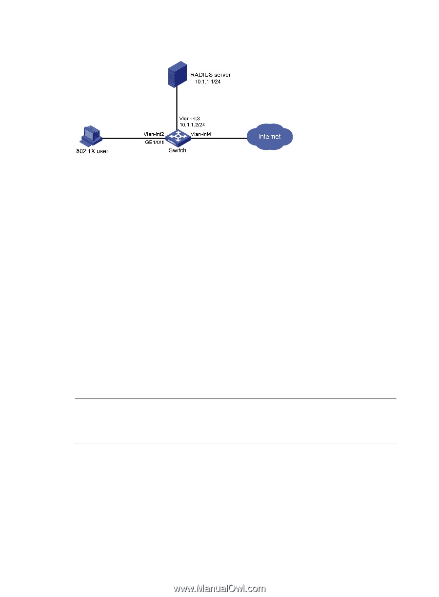
Figure 15 Network diagram Configuration prerequisites Configure the interfaces and VLANs as shown in Figure 15. Make sure the host can get a new IP address manually or automatically and can access resources in the authorized VLAN after passing authentication. Configuring the RADIUS server This example assumes that the RADIUS server runs on IMC PLAT 5.0 (E0101) and IMC UAM 5.0 (E0101). 1. Add the switch to IMC as an access device: a. Log in to IMC, click the Service tab, and select User Access Manager > Access Device from the navigation tree. b. Click Add. c. Configure the following parameters: Set the shared key for secure authentication and accounting communication to expert. Specify the ports for authentication and accounting as 1812 and 1813, respectively. Select LAN Access Service as the service type. Select HP as the access device type. Select the switch from the device list or manually add the switch whose IP address is 10.1.1.2. Leave the default settings in other fields. d. Click OK. NOTE: The IP address of the access device specified here must be the same as the source IP address of the RADIUS packets sent from the switch, which is the IP address of the outbound interface by default, or otherwise the IP address specified with the nas-ip or radius nas-ip command on the switch. 52
-
 1
1 -
2
-
3
-
4
-
5
-
6
-
7
-
8
-
9
-
10
-
11
-
12
-
13
-
14
-
15
-
16
-
17
-
18
-
19
-
20
-
21
-
22
-
23
-
24
-
25
-
26
-
27
-
28
-
29
-
30
-
31
-
32
-
33
-
34
-
35
-
36
-
37
-
38
-
39
-
40
-
41
-
42
-
43
-
44
-
45
-
46
-
47
-
48
-
49
-
50
-
51
-
52
-
53
-
54
-
55
-
56
-
 57
57 -
 58
58 -
 59
59 -
 60
60 -
 61
61 -
 62
62 -
 63
63 -
 64
64 -
 65
65 -
 66
66 -
 67
67 -
68
-
69
-
70
-
71
-
72
-
73
-
74
-
75
-
76
-
77
-
78
-
79
-
80
-
81
-
82
-
83
-
84
-
85
-
86
-
87
-
88
-
89
-
90
-
91
-
92
-
93
-
94
-
95
-
96
-
97
-
98
-
99
-
100
-
101
-
102
-
103
-
104
-
105
-
106
-
107
-
108
-
109
-
110
-
111
-
112
-
113
-
114
-
115
-
116
-
117
-
118
-
119
-
120
-
121
-
122
-
123
-
124
-
125
-
126
-
127
-
128
-
129
-
130
-
131
-
132
-
133
-
134
-
135
-
136
-
137
-
138
-
139
-
140
-
141
-
142
-
143
-
144
-
145
-
146
-
147
-
148
-
149
-
150
-
151
-
152
-
153
-
154
-
155
-
156
-
157
-
158
-
159
-
160
-
161
-
162
-
163
-
164
-
165
-
166
-
167
-
168
-
169
-
170
-
171
-
172
-
173
-
174
-
175
-
176
-
177
-
178
-
179
-
180
-
181
-
182
-
183
-
184
-
185
-
186
-
187
-
188
-
189
-
190
-
191
-
192
-
193
-
194
-
195
-
196
-
197
-
198
-
199
-
200
-
201
-
202
-
203
-
204
-
205
-
206
-
207
-
208
-
209
-
210
-
211
-
212
-
213
-
214
-
215
-
216
-
217
-
218
-
219
-
220
-
221
-
222
-
223
-
224
-
225
-
226
-
227
-
228
-
229
-
230
-
231
-
232
-
233
-
234
-
235
-
236
-
237
-
238
-
239
-
240
-
241
-
242
-
243
-
244
-
245
-
246
-
247
-
248
-
249
-
250
-
251
-
252
-
253
-
254
-
255
-
256
-
257
-
258
-
259
-
260
-
261
-
262
-
263
-
264
-
265
-
266
-
267
-
268
-
269
-
270
-
271
-
272
-
273
-
274
-
275
-
276
-
277
-
278
-
279
-
280
-
281
-
282
-
283
-
284
-
285
 |
 |