HP Surestore 64 fw 05.01.00 and sw 07.01.00 - Director Product Manager - User - Page 90
Node Properties, Port Technology, Port number, Connector type, Transceiver type, Distance, Media
 |
View all HP Surestore 64 manuals
Add to My Manuals
Save this manual to your list of manuals |
Page 90 highlights
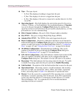
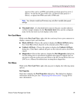
Monitoring and Managing the Director Node Properties Click this to display the Node Properties dialog box. Note that if a node is not logged into the port, a message displays indicating that node information is not available. For details on information that displays in this dialog box, refer to "Displaying Node Properties" on page 102. Port Technology Click this to display the Port Technology dialog box. This dialog box displays the following information: ■ Port number. ■ Connector type-Always LC. ■ Transceiver type-Longwave laser LC or shortwave laser LC. ■ Distance-General distance range for port transmission. This can be either short-to-long distances for the longwave laser LC transceiver or short distances for the shortwave laser LC transceivers. ■ Media-The Fibre Channel mode and optic size. For the longwave laser LC transceiver, this would be single mode 9 micron. For the shortwave laser LC transceiver, this would be multimode 50 micron or 62.5 micron. ■ Speed-This will be set to either 1 Gbit per second or 1 Gbit, 2 Gbit per second. Block Port Click to display a check mark and block port transmission. If blocked, a node attached to the port is prevented from logging into the director or communicating with other devices attached to switch ports. A blocked port continuously transmits offline signals (OLS). Click to remove the check mark and unblock the port. If unblocked, a node attached to the port can communicate with the switch and communicate with other nodes attached to the switch. Enable Beaconing Click this to make the amber LED by the port blink on the actual switch and the amber indicator blink for the port in the Hardware View. This enables users to locate the unit where the port is located. When a blinking amber LED indicator displays by a port, an attention indicator ( ) displays below the port's connector in the Port Card View and on the port card in the Hardware View. 90 Director Product Manager User Guide
-
 1
1 -
2
-
3
-
4
-
5
-
6
-
7
-
8
-
9
-
10
-
11
-
12
-
13
-
14
-
15
-
16
-
17
-
18
-
19
-
20
-
21
-
22
-
23
-
24
-
25
-
26
-
27
-
28
-
29
-
30
-
31
-
32
-
33
-
34
-
35
-
36
-
37
-
38
-
39
-
40
-
41
-
42
-
43
-
44
-
45
-
46
-
47
-
48
-
49
-
50
-
51
-
52
-
53
-
54
-
55
-
56
-
57
-
58
-
59
-
60
-
61
-
62
-
63
-
64
-
65
-
66
-
67
-
68
-
69
-
70
-
71
-
72
-
73
-
74
-
75
-
76
-
77
-
78
-
79
-
80
-
81
-
82
-
83
-
84
-
 85
85 -
 86
86 -
 87
87 -
 88
88 -
 89
89 -
 90
90 -
 91
91 -
 92
92 -
 93
93 -
 94
94 -
 95
95 -
96
-
97
-
98
-
99
-
100
-
101
-
102
-
103
-
104
-
105
-
106
-
107
-
108
-
109
-
110
-
111
-
112
-
113
-
114
-
115
-
116
-
117
-
118
-
119
-
120
-
121
-
122
-
123
-
124
-
125
-
126
-
127
-
128
-
129
-
130
-
131
-
132
-
133
-
134
-
135
-
136
-
137
-
138
-
139
-
140
-
141
-
142
-
143
-
144
-
145
-
146
-
147
-
148
-
149
-
150
-
151
-
152
-
153
-
154
-
155
-
156
-
157
-
158
-
159
-
160
-
161
-
162
-
163
-
164
-
165
-
166
-
167
-
168
-
169
-
170
-
171
-
172
-
173
-
174
-
175
-
176
-
177
-
178
-
179
-
180
-
181
-
182
-
183
-
184
-
185
-
186
-
187
-
188
-
189
-
190
-
191
-
192
-
193
-
194
-
195
-
196
-
197
-
198
-
199
-
200
-
201
-
202
-
203
-
204
-
205
-
206
-
207
-
208
-
209
-
210
-
211
-
212
-
213
-
214
-
215
-
216
-
217
-
218
-
219
-
220
-
221
-
222
-
223
-
224
-
225
-
226
-
227
-
228
-
229
-
230
-
231
-
232
-
233
-
234
-
235
-
236
-
237
-
238
-
239
-
240
-
241
-
242
-
243
-
244
 |
 |
