Lexmark X342N Service Manual - Page 43
Controller card service check, Controller card on LVPS/HVPS, service check
 |
UPC - 734646256292
View all Lexmark X342N manuals
Add to My Manuals
Save this manual to your list of manuals |
Page 43 highlights
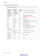
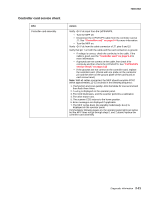
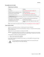
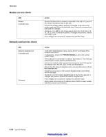
Controller card service check FRU Controller card assembly 7003-XXX Action Verify +24 V dc input from the LVPS/HVPS. • Turn the MFP off. • Disconnect the LVPS/HVPS cable from the controller card at J7. See "Controller card" on page 5-4 for more information. • Turn the MFP on. Verify +24 V dc from the cable connector of J7, pins 9 and 10. Verify that pin 7 on both the cable and the card connectors is ground. • If voltage is correct, check the continuity in the cable. If the cable is good, see the "Controller card" on page 5-4 for more information. • If grounds are not correct on the cable, first check it for continuity and then check the LVPS/HVPS. See "LVPS/HVPS service check" on page 2-25 • If the grounds are not correct on the controller card, replace the controller card. (Check with one probe on the connector pin and the other on the ground plane of the card found at each screw head.) Note: With all cables connected, the MFP should complete POST within approximately 12-15 seconds in the following sequence: 1. The function and scan quality LEDs illuminate for one second and then flash three times. 2. Loading is displayed on the operator panel. 3. The CCD illuminates, and the scanner performs a calibration. 4. The drive motor runs. 5. The scanner CCD returns to the home position. 6. Error messages are displayed if applicable. 7. The MFP cycles down into standby mode/ready. Ready is displayed on the operator panel. If immediately following power-on, the operator panel lights are active but the MFP does not go through steps 1 and 2 above, replace the controller card assembly. Diagnostic information 2-21
-
 1
1 -
2
-
3
-
4
-
5
-
6
-
7
-
8
-
9
-
10
-
11
-
12
-
13
-
14
-
15
-
16
-
17
-
18
-
19
-
20
-
21
-
22
-
23
-
24
-
25
-
26
-
27
-
28
-
29
-
30
-
31
-
32
-
33
-
34
-
35
-
36
-
37
-
 38
38 -
 39
39 -
 40
40 -
 41
41 -
 42
42 -
 43
43 -
 44
44 -
 45
45 -
 46
46 -
 47
47 -
 48
48 -
49
-
50
-
51
-
52
-
53
-
54
-
55
-
56
-
57
-
58
-
59
-
60
-
61
-
62
-
63
-
64
-
65
-
66
-
67
-
68
-
69
-
70
-
71
-
72
-
73
-
74
-
75
-
76
-
77
-
78
-
79
-
80
-
81
-
82
-
83
-
84
-
85
-
86
-
87
-
88
-
89
-
90
-
91
-
92
-
93
-
94
-
95
-
96
-
97
-
98
-
99
-
100
-
101
-
102
-
103
-
104
-
105
-
106
-
107
-
108
-
109
-
110
-
111
-
112
-
113
-
114
-
115
-
116
-
117
-
118
-
119
-
120
-
121
-
122
-
123
-
124
-
125
-
126
-
127
-
128
-
129
-
130
-
131
-
132
-
133
-
134
-
135
-
136
-
137
-
138
-
139
-
140
-
141
-
142
-
143
-
144
-
145
-
146
-
147
-
148
-
149
-
150
-
151
-
152
-
153
-
154
-
155
-
156
-
157
-
158
-
159
-
160
-
161
-
162
-
163
 |
 |
