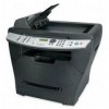
Lexmark X342N Service Manual - Page 49
Operator panel service check, Action, Buttons, Lights
 |
UPC - 734646256292
View all Lexmark X342N manuals
Add to My Manuals
Save this manual to your list of manuals |
Page 49 highlights
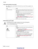
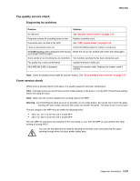
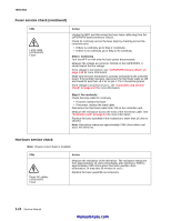
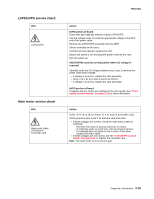
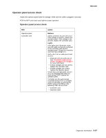
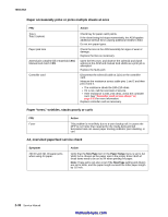
Operator panel service check Inspect the operator panel cable for damage. Make sure the cable is plugged in securely. POR the MFP, and check each light for proper operation. Operator panel service check FRU Operator panel Controller card Action Buttons Check connector J5, pin 5 for 3.3 V. If the voltage is present, replace the operator panel. If the voltage is not present, replace the controller card. Lights If the lights don't illuminate, make sure the cable is properly connected to the controller card and the operator panel. Ensure the controller card has input voltage to it. Verify +24 V dc on cable pins 9 and 10 at J7. • Check for +5 V dc at J5, pin 14. See "Controller card service check" on page 2-21 or page 4 for more information. • If these voltages are not correct, replace the controller card. • If these voltages are correct, replace the operator panel. If more than one light does not turn on or an individual light stays on solid during POST, replace the operator panel. If all lights are dim and operate erratically during POST or all lights come on and stay on solid during POST, replace the FRUs in the following order one at a time: • Controller card • Operator panel 7003-XXX Diagnostic information 2-27
-
 1
1 -
2
-
3
-
4
-
5
-
6
-
7
-
8
-
9
-
10
-
11
-
12
-
13
-
14
-
15
-
16
-
17
-
18
-
19
-
20
-
21
-
22
-
23
-
24
-
25
-
26
-
27
-
28
-
29
-
30
-
31
-
32
-
33
-
34
-
35
-
36
-
37
-
38
-
39
-
40
-
41
-
42
-
43
-
 44
44 -
 45
45 -
 46
46 -
 47
47 -
 48
48 -
 49
49 -
 50
50 -
 51
51 -
 52
52 -
 53
53 -
 54
54 -
55
-
56
-
57
-
58
-
59
-
60
-
61
-
62
-
63
-
64
-
65
-
66
-
67
-
68
-
69
-
70
-
71
-
72
-
73
-
74
-
75
-
76
-
77
-
78
-
79
-
80
-
81
-
82
-
83
-
84
-
85
-
86
-
87
-
88
-
89
-
90
-
91
-
92
-
93
-
94
-
95
-
96
-
97
-
98
-
99
-
100
-
101
-
102
-
103
-
104
-
105
-
106
-
107
-
108
-
109
-
110
-
111
-
112
-
113
-
114
-
115
-
116
-
117
-
118
-
119
-
120
-
121
-
122
-
123
-
124
-
125
-
126
-
127
-
128
-
129
-
130
-
131
-
132
-
133
-
134
-
135
-
136
-
137
-
138
-
139
-
140
-
141
-
142
-
143
-
144
-
145
-
146
-
147
-
148
-
149
-
150
-
151
-
152
-
153
-
154
-
155
-
156
-
157
-
158
-
159
-
160
-
161
-
162
-
163
 |
 |