Lexmark X342N Service Manual - Page 95
Input roller clutch and lever removal (autocompensator clutch
 |
UPC - 734646256292
View all Lexmark X342N manuals
Add to My Manuals
Save this manual to your list of manuals |
Page 95 highlights
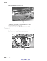
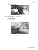
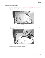
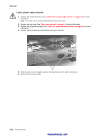
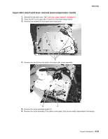
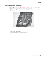
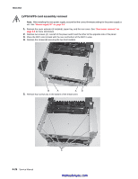
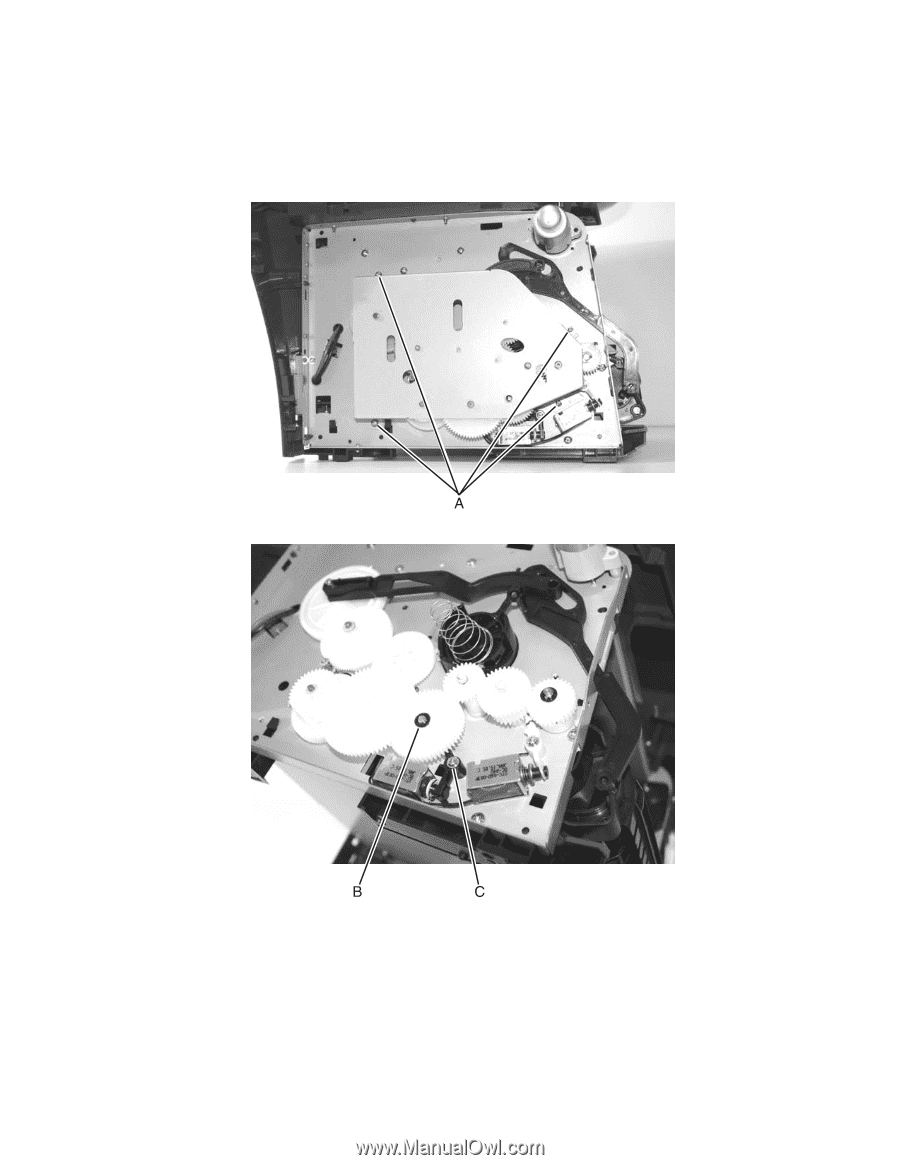
Input roller clutch and lever removal (autocompensator clutch) 1. Remove the left side cover. See "Left side cover removal" on page 4-3. 2. Place the MFP on its right side. Protect the cover from being marred. 3. Remove four screws (A) in the gear train metal cover. 7003-XXX 4. Remove the clip (B) from the shaft of the input roller clutch assembly. 5. Remove the screw and lever (pawl) (C). 6. Remove the clutch assembly. If the pieces come apart, they can be easily reassembled if necessary. Repair information 4-23
-
 1
1 -
2
-
3
-
4
-
5
-
6
-
7
-
8
-
9
-
10
-
11
-
12
-
13
-
14
-
15
-
16
-
17
-
18
-
19
-
20
-
21
-
22
-
23
-
24
-
25
-
26
-
27
-
28
-
29
-
30
-
31
-
32
-
33
-
34
-
35
-
36
-
37
-
38
-
39
-
40
-
41
-
42
-
43
-
44
-
45
-
46
-
47
-
48
-
49
-
50
-
51
-
52
-
53
-
54
-
55
-
56
-
57
-
58
-
59
-
60
-
61
-
62
-
63
-
64
-
65
-
66
-
67
-
68
-
69
-
70
-
71
-
72
-
73
-
74
-
75
-
76
-
77
-
78
-
79
-
80
-
81
-
82
-
83
-
84
-
85
-
86
-
87
-
88
-
89
-
 90
90 -
 91
91 -
 92
92 -
 93
93 -
 94
94 -
 95
95 -
 96
96 -
 97
97 -
 98
98 -
 99
99 -
 100
100 -
101
-
102
-
103
-
104
-
105
-
106
-
107
-
108
-
109
-
110
-
111
-
112
-
113
-
114
-
115
-
116
-
117
-
118
-
119
-
120
-
121
-
122
-
123
-
124
-
125
-
126
-
127
-
128
-
129
-
130
-
131
-
132
-
133
-
134
-
135
-
136
-
137
-
138
-
139
-
140
-
141
-
142
-
143
-
144
-
145
-
146
-
147
-
148
-
149
-
150
-
151
-
152
-
153
-
154
-
155
-
156
-
157
-
158
-
159
-
160
-
161
-
162
-
163
 |
 |
Repair information
4-23
7003-XXX
Input roller clutch and lever removal (autocompensator clutch)
1.
Remove the left side cover. See
“Left side cover removal” on page 4-3
.
2.
Place the MFP on its right side. Protect the cover from being marred.
3.
Remove four screws (A) in the gear train metal cover.
4.
Remove the clip (B) from the shaft of the input roller clutch assembly.
5.
Remove the screw and lever (pawl) (C).
6.
Remove the clutch assembly. If the pieces come apart, they can be easily reassembled if necessary.