Netgear WC7500-Wireless User Manual
Netgear WC7500-Wireless Manual
 |
View all Netgear WC7500-Wireless manuals
Add to My Manuals
Save this manual to your list of manuals |
Netgear WC7500-Wireless manual content summary:
- Netgear WC7500-Wireless | User Manual - Page 1
ProSAFE Wireless Controller Models WC7500, WC7600, WC7600v2, and WC9500 User Manual November 2016 202-11659-03 350 East Plumeria Drive San Jose, CA 95134 USA - Netgear WC7500-Wireless | User Manual - Page 2
to register your product, get help, access the latest downloads and user manuals, and join our community. We recommend that you use only official NETGEAR support resources. Conformity For the current EU Declaration of Conformity, visit http://kb.netgear.com/app/answers/detail/a_id/11621. Compliance - Netgear WC7500-Wireless | User Manual - Page 3
and Feature Differences 13 Model Common Features and Capabilities 14 What Can You Do With a Wireless Controller 15 Licenses 17 Maintenance and Support 17 Chapter 2 Hardware Descriptions Package Contents 19 Hardware Models WC7500 and WC7600v2 19 WC7500 and WC7600v2 Front Panel Ports and Slots - Netgear WC7500-Wireless | User Manual - Page 4
With All Its Floors 70 Use the WiFi Auto Planning Advisor to Generate an RF Plan for a Floor 70 Manually Add and Manage Access Points on a Floor Map for an RF Plan . . . . . 76 Manually Add and Manage Antennas on a Floor Map for an RF Plan 79 Display and Recalculate the WiFi Coverage - Netgear WC7500-Wireless | User Manual - Page 5
ProSAFE Wireless Controller Manage the Time Settings 101 Manage the IP, VLAN, and Link Aggregation Settings 102 Management VLAN Concepts 102 Untagged VLAN Concepts 103 Controller Link Aggregation Concepts 103 Configure the IP, VLAN, and Controller Link Aggregation Settings 104 Manage the DHCP - Netgear WC7500-Wireless | User Manual - Page 6
Concepts 203 Configure AirQual for the Basic Profile Group 203 Configure AirQual for an Advanced Profile Group 205 Manage Quality of Service for an Advanced Profile Group 207 Quality of Service Concepts 207 Configure Quality of Service for a Profile Group 208 Manage Load Balancing 210 6 - Netgear WC7500-Wireless | User Manual - Page 7
ProSAFE Wireless Controller Load Balancing Concepts 210 Configure Load Balancing 211 Manage Rate Limiting 212 Rate Limiting Concepts 212 Configure Rate Limiting for the Basic Profile Group 213 Configure Rate Limiting for an Advanced Profile Group 214 Manage the LED Behavior 215 Manage the LED - Netgear WC7500-Wireless | User Manual - Page 8
ProSAFE Wireless Controller Save the System Logs 264 Save and Clear the Logs for an Access Point 265 View Alerts and Events 267 View System Alerts 267 View Radio Frequency Events 268 View Load-Balancing Events 269 View Rate-Limit Events 271 View Redundancy Events 272 View Stacking Events - Netgear WC7500-Wireless | User Manual - Page 9
Address Configuration 362 Check the Internet Browser 363 Troubleshoot a TCP/IP Network Using the Ping Utility 363 Use the Reset Button to Restore Default Settings 364 Resolve Problems With Date and Time 364 Resolve Network Problems 365 Resolve Problems With Access Points 365 Resolve Discovery - Netgear WC7500-Wireless | User Manual - Page 10
ProSAFE Wireless Controller Appendix B Factory Default Settings, Technical Specifications, and Passwords Requirements Factory Default Settings 387 Technical Specifications Models WC7500 and WC7600v2 387 Technical Specifications Models WC7600 and WC9500 388 Password Requirements 389 Index 10 - Netgear WC7500-Wireless | User Manual - Page 11
and Support Note: For more information about the topics covered in this manual, visit the support website at netgear.com/support. Note manually. If the features or behavior of your product does not match what is described in this guide, you might need to update your firmware. Note: In this manual - Netgear WC7500-Wireless | User Manual - Page 12
wireless network from a central point, implement security features centrally, support Layer 2 and Layer 3 fast roaming, configure a guest access captive portal, and support voice over Wi-Fi (VoWi-Fi). This user manual supports models WC7500, WC7600, WC7600v2, and WC9500. For a comparison between - Netgear WC7500-Wireless | User Manual - Page 13
blacklisted clients 1G ports SFP slots USB ports WC7500 5 WC7600 10, 50 15 50 400 2,000 Stacking is not supported Not supported Not supported Not supported 41 None 2 150 6,000 Supported Supported Supported 1 2 1 WC7600v2 10, 50 WC9500 10, 50, 100, 200 50 2,000 300 9.000 150 6,000 - Netgear WC7500-Wireless | User Manual - Page 14
architecture (continued) Feature WC7500 WC7600 WC7600v2 WC9500 SD card slot 12 None 11 None Optional extra power supply Not supported Supported Not supported Supported 1. All four Gigabit Ethernet ports provide equal performance and are bonded together in Linux active-backup mode. 2. An - Netgear WC7500-Wireless | User Manual - Page 15
and captive portal access with cost and expiration accounting. - Scheduled WiFi on/off times. • Wi-Fi Multimedia Quality of Service and advanced wireless features - Wi-Fi Multimedia (WMM) support for video, audio, and voice over Wi-Fi (VoWi-Fi). - WMM power save option. - Automatic WLAN healing - Netgear WC7500-Wireless | User Manual - Page 16
wireless controllers in a stack and synchronize information between the wireless controller.1 For more information, see Chapter 12, Manage Stacking and Redundancy. 1. Model WC7500 does not support stacking. Introduction 16 - Netgear WC7500-Wireless | User Manual - Page 17
two access points. Depending on the model, you can purchase licenses in 5-, 10-, 50-, 100-, or 200-access point increments for support of multiple access points on a single wireless controller. Table 2. Purchasable license increments License increments WC7500 5 APs WC5APL-10000S 10 APs - 50 - Netgear WC7500-Wireless | User Manual - Page 18
chapter includes the following sections: • Package Contents • Hardware Models WC7500 and WC7600v2 • Hardware Models WC7600 and WC9500 • LED Functions (All Models) • Wireless Controller System Components • Supported NETGEAR Access Points • Supported NETGEAR Antennas 2 18 - Netgear WC7500-Wireless | User Manual - Page 19
One AC power cable • Rubber feet (four) with adhesive backing • One rack-mount kit • Straight-through Category 5 Ethernet cable • ProSAFE Wireless Controller Installation Guide If any of the parts are incorrect, missing, or damaged, contact your NETGEAR dealer. We recommend that you keep the carton - Netgear WC7500-Wireless | User Manual - Page 20
a DB9 male connector. The default baud rate is 115200 bits/second. Note: The console port is for debugging under guidance of NETGEAR technical support only. Reset button Using a sharp object, press and hold this button for about 10 seconds until the Status LED blinks and the wireless controller - Netgear WC7500-Wireless | User Manual - Page 21
ProSAFE Wireless Controller WC7500 and WC7600v2 Back Panel Components The wireless controller comes with a single internal power supply and internal fans. The back panel provides a Kensington™ lock slot and the AC power supply connector for the 100-240V, 3A, 50-60 Hz power supply. Kensington lock - Netgear WC7500-Wireless | User Manual - Page 22
ProSAFE Wireless Controller Hardware Models WC7600 and WC9500 The front panel ports, slots, and LEDs, back panel components, and product label of models WC7600 and WC9500 are described in the following sections. WC7600 and WC9500 Front Panel Ports and Slots The following figure shows the front panel - Netgear WC7500-Wireless | User Manual - Page 23
restored. USB port One USB 2.0 port for external storage of floor heat maps, saving of the syslogs, and backing up the configuration. The USB port supports FAT32 file systems. SFP+ slots and LEDs Two SFP+ slots for optional 10GE SFP+ or 1G SFP gigabit interface converters (GBICs), each slot with - Netgear WC7500-Wireless | User Manual - Page 24
supply LED is lit green when the power supply functions correctly. If the LED is off, power is not supplied to the power supply, or a problem occurred. • Fans. Two double fans, each of which can be easily exchanged. • Slot for optional second power supply. The cover plate can be removed so - Netgear WC7500-Wireless | User Manual - Page 25
ProSAFE Wireless Controller Figure 9. Product label WC9500 LED Functions (All Models) The function of each LED is described in the following table. These LEDS apply to all models except where noted otherwise. Table 5. LED functions for all models LED Power LED Status Solid green Off Status LED - Netgear WC7500-Wireless | User Manual - Page 26
wireless controller or a group of up to three stacked wireless controllers that can function in a redundant configuration1. The wireless controller system supports the following NETGEAR ProSAFE access point models: • WAC740 ProSAFE 4x4 Dual-Band Wireless AC Access Point • WAC730 ProSAFE 3x3 Dual - Netgear WC7500-Wireless | User Manual - Page 27
standalone access point. This model can be used only as a controller-managed access point. WAC730 All firmware versions are supported. WAC720 All firmware versions are supported. WN370 Model WN370 cannot function as a standalone access point. This model can be used only as a controller-managed - Netgear WC7500-Wireless | User Manual - Page 28
with the 802.3af standard. - Accepts optional antennas. For product documentation and firmware, visit netgear.com/support/product/WAC720. • WN370 ProSAFE Wall Mounted Wireless-N Access Point - Supports concurrently 802.11b, 802.11g, and 802.11n network devices. - Operates in the 2.4 GHz radio band - Netgear WC7500-Wireless | User Manual - Page 29
802.11b, 802.11g, and 802.11n network devices. - Operates concurrently in the 2.4 GHz and 5 GHz radio bands. - Supports speeds of up to 300 Mbps for 802.11n network devices. - Supports Power over Ethernet (PoE) with a power consumption that complies with the 802.3af or 802.3at standards. For product - Netgear WC7500-Wireless | User Manual - Page 30
- Frequency range 2400-2485 MHz - Maximum range 11.5 km (7.2 miles) - Polarization vertical For product documentation and firmware, visit netgear.com/support/product/ANT2409v2. • ANT224D10 ProSAFE 10 dBi 2x2 Indoor/Outdoor Directional Antenna - 10 dBi directional antenna for indoor or outdoor use - Netgear WC7500-Wireless | User Manual - Page 31
ProSAFE Wireless Controller - Frequency range 2400-2500 MHz - Maximum range 8.5 km (5.28 miles) - Polarization linear; vertical For product documentation and firmware, visit netgear.com/support/product/ANT224. Hardware Descriptions 31 - Netgear WC7500-Wireless | User Manual - Page 32
3. System Planning and Deployment Scenarios This chapter includes the following sections: • Basic and Advanced Setting Concepts • Profile Group Concepts • System Planning Concepts • High-Level Configuration Examples • Management VLAN and Data VLAN Strategies • High-Level Deployment Scenarios 3 32 - Netgear WC7500-Wireless | User Manual - Page 33
or business and therefore adhere to the same policies and use a few service set identifiers (SSIDs, or network names). • Advanced settings for access point policies per building or department. The access points could support different security profiles per building and department, for example, - Netgear WC7500-Wireless | User Manual - Page 34
includes all the features that you can configure for an individual access point: up to 8 profiles (16 for dual-band access points), each of which supports its own SSID, security, MAC ACL, rate-limiting settings, WMM settings, and so on. Basic Profile The basic profile includes all the settings that - Netgear WC7500-Wireless | User Manual - Page 35
architecture Security profiles The following figure shows an example of three access point profile groups, in which the first profile group (Group-1) supports five security profiles. For each profile in this profile group, the profile name, radio mode, and authentication setting are shown. (Group - Netgear WC7500-Wireless | User Manual - Page 36
are ready to configure the wireless controller. For information about how to deploy the wireless controller in your network, see your model's installation guide, which you can download by visiting downloads.netgear.com. For many configurations, you can use the default WiFi settings. The IP address - Netgear WC7500-Wireless | User Manual - Page 37
are treated as management VLAN traffic. Note: Use a tagged VLAN or change the tagged VLAN ID only if the hubs and switches on your LAN support 802.1Q. If they do not, and you did not configure a tagged VLAN with the same VLAN ID on the hubs and switches in your - Netgear WC7500-Wireless | User Manual - Page 38
Client Authentication and Data Encryption A user must authenticate to the WLAN to be able to access WLAN resources. The wireless controller supports several types of security methods, including those methods that require an external RADIUS or LDAP authentication server. The encryption option that - Netgear WC7500-Wireless | User Manual - Page 39
ProSAFE Wireless Controller High-Level Configuration Examples This section includes the following subsections: • Single Controller Configuration With Basic Profile Group • Single Controller Configuration With Advanced Profile Groups • Stacked Controller Configuration Single Controller - Netgear WC7500-Wireless | User Manual - Page 40
ProSAFE Wireless Controller Single Controller Configuration With Advanced Profile Groups A more complex configuration consists of a single wireless controller that controls a collection of access points that are organized in access point profile groups and might use several profiles in each access - Netgear WC7500-Wireless | User Manual - Page 41
ProSAFE Wireless Controller Stacked Controller Configuration A stacked controller configuration can consist of up to three wireless controllers and up to 600 access points. Note: If the stack members are on different floors or in different buildings, you could configure a separate access point - Netgear WC7500-Wireless | User Manual - Page 42
ProSAFE Wireless Controller Step Configuration Web Management Interface Path 3. Configure the slave wireless controllers and deploy them in the network. For each slave wireless controller, configure up to eight access point profile groups, and for each access point profile in a group, do at least - Netgear WC7500-Wireless | User Manual - Page 43
ProSAFE Wireless Controller The following illustration shows a simplified view of how you can use VLANs to segregate traffic by user category. Management VLAN 100 Ethernet traffic Finance VLAN 10 Ethernet traffic Employee VLAN 20 Ethernet traffic Internet Network printer Deploy the wireless - Netgear WC7500-Wireless | User Manual - Page 44
ProSAFE Wireless Controller High-Level Deployment Scenarios This section provides three deployment scenarios to illustrate how the wireless controller can function in various network configurations: • Scenario Example 1: Network With Single VLAN • Scenario Example 2: Advanced Network With VLANs - Netgear WC7500-Wireless | User Manual - Page 45
ProSAFE Wireless Controller The access points and wireless controller are connected in the same subnet and use the same IP address range that is assigned for that subnet. The configuration does not include any routers between the access points and the wireless controller. The access points are - Netgear WC7500-Wireless | User Manual - Page 46
ProSAFE Wireless Controller Step Configuration Web Management Interface Path 5. When the access points are operating, open the Discovery Wizard to do the following: Access Point > Discovery Wizard 1. Specify the state of the access points. The state can be either factory default in a Layer 2 - Netgear WC7500-Wireless | User Manual - Page 47
ProSAFE Wireless Controller The access points and wireless controller are connected in the same subnet and same VLAN and use the same IP address range that is assigned for that subnet. The configuration does not include any routers between the access points and the wireless controller. The access - Netgear WC7500-Wireless | User Manual - Page 48
the components in the wireless controller system: • One wireless controller • Fifty access points (managed by the wireless controller through management VLAN 1) 1. Model WC7500 does not support controller redundancy. System Planning and Deployment Scenarios 48 - Netgear WC7500-Wireless | User Manual - Page 49
ProSAFE Wireless Controller • One redundant wireless controller • Four VLANs: VLAN 10, VLAN 20, VLAN 30, and VLAN 40 • Three SSIDs: SSID 1, SSID 2, and SSID 3 In this scenario, the VLANs and SSIDs are used to accommodate traffic for different user groups in a school that is spread out over two - Netgear WC7500-Wireless | User Manual - Page 50
ProSAFE Wireless Controller This network configuration requires the following conditions: • VLAN 1 is configured on the wireless controllers, core switch, and PoE switches. This VLAN is untagged. • VLANs 10, 20, and 30 are configured on the wireless controllers, core switch, and the PoE switch in - Netgear WC7500-Wireless | User Manual - Page 51
ProSAFE Wireless Controller Step Configuration Web Management Interface Path 4. Deploy the access points and connect them to PoE switches. 5. When the access points are operating, open the Discovery Wizard to do the following: Access Point > Discovery Wizard 1. Specify the state of the access - Netgear WC7500-Wireless | User Manual - Page 52
and Floors for an RF Plan • Use the WiFi Auto Planning Advisor to Generate an RF Plan for a Floor • Manually Add and Manage Access Points on a Floor Map for an RF Plan • Manually Add and Manage Antennas on a Floor Map for an RF Plan • Display and Recalculate the WiFi Coverage for a Heat - Netgear WC7500-Wireless | User Manual - Page 53
ProSAFE Wireless Controller Application, Browser, and Port Requirements for RF Planning For you to be able to access the RF planning pages in the web management interface, make sure that your computer can run Adobe Flash Player and that Java is enabled in your browser. If you get a Java security - Netgear WC7500-Wireless | User Manual - Page 54
ProSAFE Wireless Controller Note: In a redundancy group, after a failover occurs to a redundant controller, RF planning is no longer accessible. Only after a switchback to the primary controller occurs, RF planning becomes available again. Planning Requirements To expedite your planning efforts, - Netgear WC7500-Wireless | User Manual - Page 55
ProSAFE Wireless Controller Table 9. Floor planning table (continued) Item Your Information Brick walls Concrete walls Light doors Metal doors Heavy doors Thin windows Thick windows Other obstacles WiFi building obstruction areas Cubicle office areas Closed office areas Elevator - Netgear WC7500-Wireless | User Manual - Page 56
: • Use the WiFi Auto Planning Advisor See Use the WiFi Auto Planning Advisor to Generate an RF Plan for a Floor on page 70. • (Optional) Manually add and fine-tune access points on each floor. See Manually Add and Manage Access Points on a Floor Map for an RF Plan on page 76. • (Optional - Netgear WC7500-Wireless | User Manual - Page 57
add up to 30 buildings, each of which can include up to 20 floors. However, the total number of floors that the wireless controller can support is 128. To add and define a building and floors: 1. Open a web browser, and in the browser's address field, type the wireless controller's IP address. By - Netgear WC7500-Wireless | User Manual - Page 58
ProSAFE Wireless Controller The Floor-1 name displays. This default floor name was added automatically when you added the building. 8. Click Floor-1. The default floor map displays. This default floor map was added automatically when you added the building. 9. To add a custom floor map, click the - Netgear WC7500-Wireless | User Manual - Page 59
ProSAFE Wireless Controller Add a Single Floor to a Building You can add a single floor to an existing building. To add a single floor to a building: 1. Open a web browser, and in the browser's address field, type the wireless controller's IP address. By default, the IP address is 192.168.0.250. - Netgear WC7500-Wireless | User Manual - Page 60
ProSAFE Wireless Controller • To specify the floor length, click the Length(Y) button, select Meter or Feet from the menu, and enter the floor length. Note: If you do not want to enter the length or width or the information is not available, you can scale the floor later (see Scale a Floor on page - Netgear WC7500-Wireless | User Manual - Page 61
ProSAFE Wireless Controller 9. Select Meter or Feet from the menu and enter the distance between the two points. 10. Click the Confirm button. The floor map is scaled. 11. Click the Save icon. Your settings are saved. Add a WiFi Coverage or WiFi Noncoverage Zone to a Floor A WiFi coverage zone on a - Netgear WC7500-Wireless | User Manual - Page 62
ProSAFE Wireless Controller 12. To add another zone, repeat Step 7 though Step 11. Remove a WiFi Coverage or Noncoverage Zone From a Floor After you add and save a WiFi coverage or noncoverage zone on a floor, you can remove it from the floor. To remove a WiFi coverage area or WiFi noncoverage - Netgear WC7500-Wireless | User Manual - Page 63
ProSAFE Wireless Controller • Concrete wall (12 dB) • Light door (4 dB) • Metal door (11 dB) • Heavy door (15 dB) • Thin window (2 dB) • Thick window 4 dB) These obstacles contribute to the WLAN signal degradation based on their construction materials and interferences. Note: Before you add a - Netgear WC7500-Wireless | User Manual - Page 64
ProSAFE Wireless Controller f. Click the Obstacle icon. g. Select the icon for the custom obstacle that you just added. 9. Select a line between two points on the map by anchoring the line at one point and releasing the line at the other point. 10. To remove the obstacle, click the Undo link, and - Netgear WC7500-Wireless | User Manual - Page 65
ProSAFE Wireless Controller Add a WiFi Obstruction Area WiFi obstructions areas can be any of the following predefined areas: • Cubicle office area • Closed office area • Elevator shaft • Warehouse stock with low density • Warehouse stock with medium density • Warehouse stock with high density These - Netgear WC7500-Wireless | User Manual - Page 66
ProSAFE Wireless Controller Remove a WiFi Obstruction Area After you add and save a WiFi obstruction area on a floor, you can remove it from the floor. To remove a WiFi obstruction area from a floor: 1. Open a web browser, and in the browser's address field, type the wireless controller's IP - Netgear WC7500-Wireless | User Manual - Page 67
ProSAFE Wireless Controller The wireless controller's web management interface opens and displays the Summary page. 4. Select Plans > Planning. The page displays the Planning icons. 5. In the building tree on the left, click the + icon of the building that contains the floor. The floor names display - Netgear WC7500-Wireless | User Manual - Page 68
ProSAFE Wireless Controller 7. Change the name. 8. Click the Confirm button. Your settings are saved. Duplicate an Entire Building With All Floors You can duplicate an entire building with all floors and floor plans, including all floor definitions. For information about duplicating a single floor - Netgear WC7500-Wireless | User Manual - Page 69
ProSAFE Wireless Controller The wireless controller's login window opens. 2. Enter your user name and password. 3. Click the Login button. The wireless controller's web management interface opens and displays the Summary page. 4. Select Plans > Layout. The page displays the Planning icons. 5. In the - Netgear WC7500-Wireless | User Manual - Page 70
ProSAFE Wireless Controller The floor names display. 6. Click the floor name. The floor map displays. 7. Click the Trashcan icon. 8. Confirm the removal. The floor is removed. Remove an Entire Building With All Its Floors You can remove an entire building with all its floors. However, you cannot - Netgear WC7500-Wireless | User Manual - Page 71
GHz or 5 GHz) • The maximum number of clients that must be supported on the floor For you to determine the expected financial investment, the optimize the WLAN network coverage and throughput for your RF plan, you can manually fine-tune the placement of access points and antennas on the floor map. - Netgear WC7500-Wireless | User Manual - Page 72
ProSAFE Wireless Controller To run the WiFi auto planning advisor and generate an RF plan and heat map for a floor: 1. Open a web browser, and in the browser's address field, type the wireless controller's IP address. By default, the IP address is 192.168.0.250. The wireless controller's login - Netgear WC7500-Wireless | User Manual - Page 73
Specify the access point that you intend to use for the floor: 1. Click the Browse button. The access points that the wireless controller supports display in a pop-up window. 2. Click the access point. All calculations are performed with the selected access point. 3. Click the Confirm button. Your - Netgear WC7500-Wireless | User Manual - Page 74
of -67 dBm and a minimum SNR of 25 dB. Band From the Band menu, select 2.4G or 5G. If the selected access point does not support the 5 GHz band, the menu selection is automatically set to 2.4G. Maximum Clients Enter the total number of clients that must be - Netgear WC7500-Wireless | User Manual - Page 75
ProSAFE Wireless Controller Signal strength at this location The WiFi auto planning advisor generates a heat map that suggests the required number of access points (15 in the figure) and the locations on the floor map to achieve the optimum WiFi coverage that is based on the WLAN requirements that - Netgear WC7500-Wireless | User Manual - Page 76
Scale a Floor on page 60) and define the WiFi coverage zone (see Add a WiFi Coverage or WiFi Noncoverage Zone to a Floor on page 61). To manually add and manage individual access points on a floor map for an RF plan: 1. Open a web browser, and in the browser's address field, type the wireless - Netgear WC7500-Wireless | User Manual - Page 77
. Specify the access point that you intend to use for the floor: 1. Click the Browse button. The access points that the wireless controller supports display in a pop-up window. 2. Click the access point. All calculations are performed with the selected access point. 3. Click the Confirm button. Your - Netgear WC7500-Wireless | User Manual - Page 78
default setting is HALF(1/2). • Antenna Gain (dBi). When you select an access point, this field is populated automatically. 5G If the selected access point supports the 5 GHz band, specify the settings for the 5 GHz band: • Enable. By default, the On radio button is selected and the 5 GHz band - Netgear WC7500-Wireless | User Manual - Page 79
channel cannot be displayed on the map. 18. To save the floor map with its new configuration, click the Save The settings are saved. icon. Manually Add and Manage Antennas on a Floor Map for an RF Plan You can add individual antennas to a floor map for an RF plan. These antennas - Netgear WC7500-Wireless | User Manual - Page 80
ProSAFE Wireless Controller To manually add and manage individual antennas on a floor map for an RF plan: 1. Open a web browser, and in the browser's address field, type the wireless controller's - Netgear WC7500-Wireless | User Manual - Page 81
, Antenna-1. Specify the antenna that you intend to use for the floor: 1. Click the Browse button. The antennas that the wireless controller supports display in a pop-up window. 2. Click the antenna. All calculations are performed with the selected antenna. 3. Click the Confirm button. Your settings - Netgear WC7500-Wireless | User Manual - Page 82
coverage. Note: Adding or removing antennas changes the heat map. 16. To switch the heat map to the 2.4 GHz or 5 GHz band (for antennas that support dual bands), on the right, click the Band icon. The Band icon displays 2.4G if the heat map for the 2.4 GHz band is shown. The - Netgear WC7500-Wireless | User Manual - Page 83
ProSAFE Wireless Controller Display and Recalculate the WiFi Coverage for a Heat Map After you set up an RF plan and generate a heat map for a floor, you can display the WiFi coverage and view how the WiFi coverage changes if you change the minimum signal strength with the same number of access - Netgear WC7500-Wireless | User Manual - Page 84
a floor displays all access points and antennas that you added by running the WiFi auto planning advisor, the access points and antennas that you added manually, or a combination of both. To display or change the access point and antenna inventory for an RF plan: 1. Open a web browser, and in the - Netgear WC7500-Wireless | User Manual - Page 85
RF Plan for a Floor on page 70), the access points that you added manually (see Manually Add and Manage Access Points on a Floor Map for an RF Plan on page , or for information about removing an access point from the inventory, see Manually Add and Manage Access Points on a Floor Map for an RF Plan - Netgear WC7500-Wireless | User Manual - Page 86
an RF Plan for a Floor on page 70), the antennas that you added manually (see Manually Add and Manage Antennas on a Floor Map for an RF Plan on page , or for information about removing an access point from the inventory, see Manually Add and Manage Antennas on a Floor Map for an RF Plan on - Netgear WC7500-Wireless | User Manual - Page 87
: • Floor summary • Inventory summary that could serve as a purchase list • Detailed list of access points • Detailed list of antennas (if you added any manually) • Floor map with suggested locations of the access points and antennas • Heat map for the 2.4 GHz band • Heat map for the 5 GHz band You - Netgear WC7500-Wireless | User Manual - Page 88
ProSAFE Wireless Controller View the Heat Map for a Deployed Floor Plan For an RF plan, you can assign access points and antennas to a building and floor. However, these access points and antennas are used only for the purpose of planning and are not actual access points and antennas. Access points - Netgear WC7500-Wireless | User Manual - Page 89
. The floor names display. 6. Click the floor name. Access points before placement 7. The first time that you view the heat map, move the access points manually on the floor map to closely match their actual physical locations on the floor by dragging each access point to the correct location on the - Netgear WC7500-Wireless | User Manual - Page 90
ProSAFE Wireless Controller 9. To generate the heat map for the 5 GHz band, on the right, click the Band icon. The heat map for the 5 GHz band is generated and displays. Use the color information on the right as guidance for WiFi coverage. 10. To see the information about an individual access point - Netgear WC7500-Wireless | User Manual - Page 91
5. Installation and Configuration Overview This chapter includes the following sections: • Connect Your Computer to the Wireless Controller • Log In to the Wireless Controller • Roadmap for Initial Configuration • Roadmap for Configuring Management of Your WiFi Network • Choose a Location for the - Netgear WC7500-Wireless | User Manual - Page 92
To connect to the wireless controller for initial configuration, follow the steps in this section. You can also download your model's installation guide by visiting downloads.netgear.com. To connect your computer to the wireless controller: 1. Configure the computer with a static IP address of 192 - Netgear WC7500-Wireless | User Manual - Page 93
ProSAFE Wireless Controller To log in to the wireless controller: 1. Open your browser and type http://192.168.0.250 in the browser's address field. 2. When prompted, enter admin for the user name and password for the password, both in lowercase letters. 3. Click the Login button. The first time - Netgear WC7500-Wireless | User Manual - Page 94
ProSAFE Wireless Controller In the Old Password field, the old password is automatically entered. 5. In the New Password field, enter your new password and repeat it in the Confirm New Password field. Note: You cannot change the default user name (admin), but you can create a new administrative - Netgear WC7500-Wireless | User Manual - Page 95
the VLAN (802.1Q) standard. Likewise, change the untagged VLAN value only if the hubs and switches in your network support the VLAN (802.1Q) standard. For more information, see Manage the IP, VLAN, and Link Aggregation Settings on page 102. 12. Click the Apply button. - Netgear WC7500-Wireless | User Manual - Page 96
ProSAFE Wireless Controller Your settings are saved. 13. If your network does not include a DHCP server, configure the wireless controller's DHCP server. For more information, see Manage the DHCP Server on page 106. 14. Click the Apply button. Your settings are saved. The connection to the wireless - Netgear WC7500-Wireless | User Manual - Page 97
ProSAFE Wireless Controller 6. (Optional but recommended) Configure logs, alerts, and alarms. For more information, see Configure Syslog, Alarm Notification, and Email Settings on page 114. 7. Configure security profiles: a. Configure the security profiles for the basic profile group or for advanced - Netgear WC7500-Wireless | User Manual - Page 98
wireless controller and plug the power cord into a power outlet. The Power, Status, and Ethernet LEDs light. If any of these do not light, see Troubleshoot Basic Functioning on page 361. Installation and Configuration Overview 98 - Netgear WC7500-Wireless | User Manual - Page 99
6. Configure the System and Network Settings and Register the Licenses 6 This chapter includes the following sections: • Configure the General Settings • Manage the Time Settings • Manage the IP, VLAN, and Link Aggregation Settings • Manage the DHCP Server • Register Your Licenses • Manage - Netgear WC7500-Wireless | User Manual - Page 100
ProSAFE Wireless Controller Configure the General Settings Note: You must select the correct country or region of operation. It might not be legal to operate the access points in a country or region not shown here. If your location is not listed, check with your local government agency or check the - Netgear WC7500-Wireless | User Manual - Page 101
ProSAFE Wireless Controller 5. Configure the settings as described in the following table. Setting Name Country/Region Controller Location Code Description Enter a unique value as the wireless controller name. We recommend changing the name as soon as possible after setting up. The name must - Netgear WC7500-Wireless | User Manual - Page 102
ProSAFE Wireless Controller 4. Select Configuration > System > Time. 5. Configure the settings as described in the following table. Setting Description Time Zone From the menu, select the local time zone for your country or region. Current Time This field is a nonconfigurable field that - Netgear WC7500-Wireless | User Manual - Page 103
if the hubs and switches on your network are not configured with the corresponding VLANs. Controller Link Aggregation Concepts Note: Link aggregation is not supported on model WC7500 and model WC7600v2. If you connect the two 10GE connections of the wireless controller to a switch or router, the - Netgear WC7500-Wireless | User Manual - Page 104
ProSAFE Wireless Controller Configure the IP, VLAN, and Controller Link Aggregation Settings Note: Link aggregation is not supported on model WC7500 and model WC7600v2. You can configure the management IP address, VLAN settings, and link aggregation (LAG) settings of the wireless controller. To - Netgear WC7500-Wireless | User Manual - Page 105
to use. WINS Server Enter the IP address of the Windows Internet Name Service (WINS) that you want to use. Management VLAN Settings section Management VLAN Link Aggregation Concepts on page 103. 1. Link aggregation is not supported on model WC7500 and model WC7600v2. 6. Click the Apply button. - Netgear WC7500-Wireless | User Manual - Page 106
ProSAFE Wireless Controller Manage the DHCP Server Note: Make sure that a DHCP server is available; otherwise, the Discovery Wizard does not function correctly. If your network already includes a DHCP server, do not enable the DHCP server on the wireless controller. The wireless controller can - Netgear WC7500-Wireless | User Manual - Page 107
to allow the DHCP server to function with multiple VLANs. Enter the DHCP server VLAN ID. The range is between 1 and 4094. The DHCP server services this VLAN. Configure the System and Network Settings and Register the Licenses 107 - Netgear WC7500-Wireless | User Manual - Page 108
ProSAFE Wireless Controller Setting Description IP Network Enter the IP address for the wireless controller in the VLAN that you specified in the VLAN field. Note: If you do not select the Use VLAN Interface check box, the IP address of the wireless controller's management VLAN is used. Subnet - Netgear WC7500-Wireless | User Manual - Page 109
ProSAFE Wireless Controller 5. Select the radio button in the Edit/Remove column that corresponds to the DHCP server for which you want to change the settings. 6. Click the Edit button. 7. Change the settings. 8. Click the Apply button. Your settings are saved. Remove a DHCP Server You can remove a - Netgear WC7500-Wireless | User Manual - Page 110
ProSAFE Wireless Controller Register Your Licenses Make sure that your licenses cover the number of access points in your network. Before you can register your licenses, you must configure the license server settings. Note: When you install your licenses, they replace the default trial license. For - Netgear WC7500-Wireless | User Manual - Page 111
ProSAFE Wireless Controller 6. Configure the settings as described in the following table. Setting Description Update From Select one of the following radio buttons to specify the license update server: • Default Update Server. The default license update server is used. • Specify Update Server. - Netgear WC7500-Wireless | User Manual - Page 112
ProSAFE Wireless Controller The following figure shows some licenses already registered and installed. If you register licenses for the first time, the page does not yet show any licenses. 7. Complete the fields in the Customer Information section with the customer information that is associated - Netgear WC7500-Wireless | User Manual - Page 113
ProSAFE Wireless Controller These fields are self-explanatory. 9. In the Registration Key field at the top of the page, enter the registration key for the license that you want to add and register. 10. Click the Add button. The license is added to the table. The key details in the table mean the - Netgear WC7500-Wireless | User Manual - Page 114
ProSAFE Wireless Controller 5. Configure the settings as described in the following table. Setting Description Password Enter the password for wireless controller certificates. Controller Key Click the Browse button, and select the controller key. Controller Certificate Click the Browse - Netgear WC7500-Wireless | User Manual - Page 115
ProSAFE Wireless Controller To configure the syslog settings for an internal location: 1. Open a web browser, and in the browser's address field, type the wireless controller's IP address. By default, the IP address is 192.168.0.250. The wireless controller's login window opens. 2. Enter your user - Netgear WC7500-Wireless | User Manual - Page 116
the IP address of the syslog server on the wireless controller, make sure that you set up a syslog server (such as a computer running a syslog service) and that the syslog server is available on the network. To configure the syslog settings for an external location: 1. Open a web browser, and in - Netgear WC7500-Wireless | User Manual - Page 117
configure the IP address of the syslog server on the wireless controller, make sure that you set up a syslog server (such as a computer running a syslog service) and that the syslog server is available on the network. Server Port Number Enter the number of the port at which your syslog server is - Netgear WC7500-Wireless | User Manual - Page 118
ProSAFE Wireless Controller Configure Alarm Notification Settings You can classify certain events as critical, major, normal, or minor. Some events you can classify only as critical or major. To configure alarm actions: 1. Open a web browser, and in the browser's address field, type the wireless - Netgear WC7500-Wireless | User Manual - Page 119
ProSAFE Wireless Controller Configure the Email Notification Server The email notification server is the location from which the email alerts originate. To configure email settings: 1. Open a web browser, and in the browser's address field, type the wireless controller's IP address. By default, - Netgear WC7500-Wireless | User Manual - Page 120
7. Manage Security Profiles and Profile Groups 7 This chapter includes the following sections: • WiFi Security Profile Concepts • Manage Security Profiles for the Basic Profile Group • Manage Security Profiles for Advanced Profile Groups • Network Authentication and Data Encryption Options • - Netgear WC7500-Wireless | User Manual - Page 121
radio parameters, load-balancing parameters, and rate-limit parameters. Each WiFi radio on an access point can support 8 profiles. For example, the dual-band WNDAP660 access point can support a total of 16 profiles. Therefore, in one profile group on the wireless controller, you can configure up - Netgear WC7500-Wireless | User Manual - Page 122
up to 16 profiles for a dual-band access point, or 8 profiles for a single-band access point. Using dual-band access points, the wireless controller could support a total of 128 profiles. Each profile provides its own SSID and can provide its own VLAN to allow the profile to establish its own tunnel - Netgear WC7500-Wireless | User Manual - Page 123
ProSAFE Wireless Controller Note: You can configure profiles to function with different authentication servers. For example, you could set up a guest profile with no authentication, an engineering profile that uses external RADIUS authentication, and a marketing profile that uses external LDAP - Netgear WC7500-Wireless | User Manual - Page 124
ProSAFE Wireless Controller • Advanced security settings. You can apply the following security settings to any profile, whether in the basic profile group or in an advanced profile group: - Advanced MAC authentication (the MAC ACLs that are, by default, called Acl-1, Acl-2, Acl-3, and so on; you can - Netgear WC7500-Wireless | User Manual - Page 125
ProSAFE Wireless Controller Click + to add another profile. Your selection from the Network Authentication menu determines the information that is displayed onscreen. Select the Local radio button to display the Local MAC ACL Group menu. Select the External radio button to display the External - Netgear WC7500-Wireless | User Manual - Page 126
ProSAFE Wireless Controller The newly created profile displays onscreen, and the tab for the new profile is automatically selected to let you configure the new profile. Note: The authentication server settings that you specify on the Authentication Server page affect the selections that are - Netgear WC7500-Wireless | User Manual - Page 127
ProSAFE Wireless Controller Setting Description Authentication Settings section Note: The options that display onscreen depend on the selection from Network Authentication menu. Note: The MAC ACL button displays only when you select Open System, Shared Key, WPA-PSK, WPA2-PSK, or WPA-PSK & WPA2- - Netgear WC7500-Wireless | User Manual - Page 128
Enable radio button, which is the default setting. Select the Disable button to disable the feature. For more information, see Manage Quality of Service for an Advanced Profile Group on page 207. WMM Powersave The WMM Powersave feature saves power for battery-powered equipment by increasing the - Netgear WC7500-Wireless | User Manual - Page 129
ProSAFE Wireless Controller For information about how to change the settings, see Configure a Profile in the Basic Profile Group on page 124. 8. Click the Apply button. Your settings are saved. Remove a Profile From the Basic Profile Group You can remove a profile from the basic profile group. To - Netgear WC7500-Wireless | User Manual - Page 130
ProSAFE Wireless Controller To add an advanced profile group: 1. Open a web browser, and in the browser's address field, type the wireless controller's IP address. By default, the IP address is 192.168.0.250. The wireless controller's login window opens. 2. Enter your user name and password. 3. - Netgear WC7500-Wireless | User Manual - Page 131
ProSAFE Wireless Controller Remove an Advanced Profile Group You can remove an advanced profile group To remove an advanced profile group: 1. Open a web browser, and in the browser's address field, type the wireless controller's IP address. By default, the IP address is 192.168.0.250. The wireless - Netgear WC7500-Wireless | User Manual - Page 132
ProSAFE Wireless Controller 4. Select Configuration > Profile > Advanced > Radio. The Profile Groups page displays. 5. Click the Edit button. The Edit Profile (Group-X) page displays. 6. Click the tab for the radio that for which you want to add a profile. 7. Click the + button to add the profile to - Netgear WC7500-Wireless | User Manual - Page 133
ProSAFE Wireless Controller The newly created profile displays onscreen, and the tab for the new profile is automatically selected to let you configure the new profile. Note: The authentication server settings that you specify on the Authentication Server page affect the selections that are - Netgear WC7500-Wireless | User Manual - Page 134
ProSAFE Wireless Controller Setting Description Authentication Settings section Note: The options that display onscreen depend on the selection from Network Authentication menu. Note: The MAC ACL MAC ACL buttons displays only when you select Open System, Shared Key, WPA-PSK, WPA2-PSK, or - Netgear WC7500-Wireless | User Manual - Page 135
Enable radio button, which is the default setting. Select the Disable button to disable the feature. For more information, see Manage Quality of Service for an Advanced Profile Group on page 207. WMM Powersave The WMM Powersave feature saves power for battery-powered equipment by increasing the - Netgear WC7500-Wireless | User Manual - Page 136
ProSAFE Wireless Controller 7. Click the tab for the radio for which you want to change a profile. 8. Click the tab for the profile that you want to change. 9. Change the settings. For information about how to change the settings, see Configure a Profile in an Advanced Profile Group on page 131. 10. - Netgear WC7500-Wireless | User Manual - Page 137
ProSAFE Wireless Controller Network Authentication and Data Encryption Options This section describes the detailed network authentication and data encryption options that you can select in the procedures that are described in Configure a Profile in the Basic Profile Group on page 124 and Configure - Netgear WC7500-Wireless | User Manual - Page 138
40/64-bit encryption. - 128-bit WEP. Uses 104/128-bit encryption. - 152-bit WEP. A proprietary mode that works only with other WiFi devices that support this mode. 2. To display the characters in the key fields, select the Show Key check box. 3. Select a key radio button (Key1, Key2, Key3, or Key4 - Netgear WC7500-Wireless | User Manual - Page 139
Authentication Servers and Authentication Server Groups on page 140. From the Data Encryption menu, select the type of encryption: - AES. Supports AES only. - TKIP + AES. Supports both TKIP and AES. 2. Select the Local or External radio button. 3. If you select the External radio button, select the - Netgear WC7500-Wireless | User Manual - Page 140
(Network Key) field. Note: The Data Encryption menu displays TKIP + AES, which is the only available option. Both TKIP and AES are supported. Note: For information about requirements for a WPA passphrase, see Table 15 on page 389. Manage Authentication Servers and Authentication Server Groups You - Netgear WC7500-Wireless | User Manual - Page 141
ProSAFE Wireless Controller option during the configuration of a profile. As part of the advanced authentication server settings, you can define multiple external RADIUS servers that you would typically use in a more complex network with many profiles. You can then assign different RADIUS servers to - Netgear WC7500-Wireless | User Manual - Page 142
ProSAFE Wireless Controller Configure Basic Authentication Server Settings Use the basic Authentication Server page to set up the internal authentication server, the basic external RADIUS server (which is called Auth-basic), and the external LDAP server (which is called Auth-LDAP). After you set up - Netgear WC7500-Wireless | User Manual - Page 143
ProSAFE Wireless Controller Setting External RADIUS Server Description Enable Authentication Select the Enable Authentication check box to enable authentication. Enable Accounting Select the Enable Accounting check box to enable accounting. Primary Server Secondary Server Do the following for - Netgear WC7500-Wireless | User Manual - Page 144
ProSAFE Wireless Controller For information about how to add an authentication server to a security profile in the basic profile group, see Configure a Profile in the Basic Profile Group on page 124. For information about how to add an authentication server to a security profile in an advanced - Netgear WC7500-Wireless | User Manual - Page 145
ProSAFE Wireless Controller The new authentication group displays on the advanced Authentication Server page, and the tab for the new authentication is automatically selected to let you configure the new group. 6. In the Group Name field, enter a unique name for the authentication group. By default, - Netgear WC7500-Wireless | User Manual - Page 146
the basic MAC authentication group to any profile, whether in the basic profile group or in an advanced profile group. The wireless controller supports a maximum of 4,096 MAC addresses per SSID. Note: You cannot add multicast or broadcast MAC addresses to a MAC access control list (ACL). Manage - Netgear WC7500-Wireless | User Manual - Page 147
ProSAFE Wireless Controller To set up basic MAC authentication ACL: 1. Open a web browser, and in the browser's address field, type the wireless controller's IP address. By default, the IP address is 192.168.0.250. The wireless controller's login window opens. 2. Enter your user name and password. - Netgear WC7500-Wireless | User Manual - Page 148
ProSAFE Wireless Controller 7. Click the Apply button. Your settings are saved. Remove a MAC Address From a Wireless Client List You can remove a MAC address from a wireless clients list. To remove a MAC address from a wireless clients list: 1. Open a web browser, and in the browser's address - Netgear WC7500-Wireless | User Manual - Page 149
the basic MAC authentication group, to any profile, whether in the basic profile group or in an advanced profile group. The wireless controller supports a maximum of 4,096 MAC addresses per SSID. Note: You cannot add multicast or broadcast MAC addresses to a MAC access control list (ACL). Manage - Netgear WC7500-Wireless | User Manual - Page 150
ProSAFE Wireless Controller To set up a MAC authentication group: 1. Open a web browser, and in the browser's address field, type the wireless controller's IP address. By default, the IP address is 192.168.0.250. The wireless controller's login window opens. 2. Enter your user name and password. - Netgear WC7500-Wireless | User Manual - Page 151
ProSAFE Wireless Controller For information about how to add a MAC authentication group to a security profile in the basic profile group, see Configure a Profile in the Basic Profile Group on page 124. For information about how to add a MAC authentication group to a security profile in an advanced - Netgear WC7500-Wireless | User Manual - Page 152
ProSAFE Wireless Controller 3. Enter your user name and password. 4. Click the Login button. The wireless controller's web management interface opens and displays the Summary page. 5. Select Configuration > Profile > Basic > Radio. The Edit Profile (Basic) page displays. 6. Click the tab for the - Netgear WC7500-Wireless | User Manual - Page 153
ProSAFE Wireless Controller By default, the IP address is 192.168.0.250. The wireless controller's login window opens. 3. Enter your user name and password. 4. Click the Login button. The wireless controller's web management interface opens and displays the Summary page. 5. Select Configuration > - Netgear WC7500-Wireless | User Manual - Page 154
8. Discover and Manage Access Points 8 This chapter includes the following sections: • Access Point Discovery Guidelines • Discover Access Points With the Discovery Wizard • Manage the Managed AP List • Assign Access Points to Buildings, Floors, and Advanced Profile Groups IMPORTANT: Before you - Netgear WC7500-Wireless | User Manual - Page 155
For information about the minimum required standalone firmware versions, see Supported NETGEAR Access Points on page 27. After the access points IP address, access the web management interface of the access point and manually enter the IP address of the wireless controller in the Controller IP field - Netgear WC7500-Wireless | User Manual - Page 156
ProSAFE Wireless Controller them is discovered at a time. You must add the access point to the managed list, change its IP address, and run discovery again to discover the next access point with that IP address. • Enable DHCP option 43 (vendor-specific information) on an external DHCP server. - Netgear WC7500-Wireless | User Manual - Page 157
by Network Time Protocol (NTP). • UDP port 138. Used by NetBIOS datagram service. • UDP port 161. Used by the SNMP discovery process. • UDP port 6650 the remote access point. • UDP port 7000. Used for Layer 3 roaming support. • UDP port 7890. Used by the multicast discovery process. This port does - Netgear WC7500-Wireless | User Manual - Page 158
Discovery The following limitations apply after remote access points are discovered: • Seamless Layer 2 roaming is supported for the clients of a remote access points, but seamless Layer 3 roaming is not supported for the clients across remote access points. When clients move from one IP subnet to - Netgear WC7500-Wireless | User Manual - Page 159
ProSAFE Wireless Controller - If the access point is rebooted, it loses its configuration. After the connection with the wireless controller is reestablished, the remote access point functions once again as a managed access point. Discover Access Points With the Discovery Wizard The Discovery Wizard - Netgear WC7500-Wireless | User Manual - Page 160
Click the Next button. The wireless controller searches for NETGEAR products on the LAN based on MAC address and identifies which products are supported access point models. Progress bars show the progress of the discovery process. When the discovery process is finished, the total number of access - Netgear WC7500-Wireless | User Manual - Page 161
wireless controller. For information about the wireless controller's DHCP server, see Manage the DHCP Server on page 106. • For more information, see Resolve Problems With Access Points on page 365. 9. To run the discovery process again, click the Restart button. 10. To designate an access point as - Netgear WC7500-Wireless | User Manual - Page 162
ProSAFE Wireless Controller 12. Click the Add button. Depending on the type of access points that were discovered, a page that lets you enter or ignore a login name and a password might display. 13. If necessary, enter the login name and password. The Managed AP List page displays. Because this page - Netgear WC7500-Wireless | User Manual - Page 163
Controller If one or more access points do not transition to the Connected state (see the Status column in the Managed AP List), see Resolve Problems With Access Points on page 365. For information about how to manage the Managed AP List, see Manage the Managed AP List on page 167 - Netgear WC7500-Wireless | User Manual - Page 164
ProSAFE Wireless Controller 5. Select the Installed and working in Standalone Mode radio button. Note: The I am not sure radio button directs you to the product documentation. 6. Click the Next button. 7. In the Range 1 section, fill in the Start IP and End IP fields. These IP addresses specify the - Netgear WC7500-Wireless | User Manual - Page 165
the LAN based on MAC address and then identifies which products are supported access point models. A progress bar show the progress of the the next access point with that IP address. • For more information, see Resolve Problems With Access Points on page 365. 12. To run the discovery process again, - Netgear WC7500-Wireless | User Manual - Page 166
ProSAFE Wireless Controller 13. To designate an access point as a remote access point, from the Site menu, select Remote. By default, all discovered access points are designated as Local. The Remote and Local designations are for organization only. Note: The wireless controller cannot discover - Netgear WC7500-Wireless | User Manual - Page 167
278. If one or more access points do not transition to the Connected state (see the Status column in the Managed AP List), see Resolve Problems With Access Points on page 365. For information about how to manage the Managed AP List, see Manage the Managed AP List on page 167 - Netgear WC7500-Wireless | User Manual - Page 168
ProSAFE Wireless Controller The wireless controller's login window opens. 2. Enter your user name and password. 3. Click the Login button. The wireless controller's web management interface opens and displays the Summary page. 4. Select Access Point > Managed AP List. The Managed AP List page - Netgear WC7500-Wireless | User Manual - Page 169
's IP address and network connectivity. For more information, see Resolve Problems With Access Points on page 365. Shows whether you designated the AP List on page 170. The WiFi modes that the access point supports. Note: Capability information lets you determine which access points are 802.11n - Netgear WC7500-Wireless | User Manual - Page 170
you can change the general information, IP settings, and VLAN settings, you can switch between the internal and external antenna (if the access point supports an external antenna), and you can enter location information. For a WAC740 access point that is on the managed list, you can also enable link - Netgear WC7500-Wireless | User Manual - Page 171
ProSAFE Wireless Controller 7. Configure the settings as described in the following table. Setting Description Access Point Info section Name Enter a unique value that indicates the access point name. By default, the name is netgearxxxxxx, where xxxxxx represents the last six hexadecimal - Netgear WC7500-Wireless | User Manual - Page 172
enable radio button. By default, the disable radio button is selected and link aggregation is disabled. Note: Link aggregation for access point Ethernet ports is supported only for a WAC740 access point. Discover and Manage Access Points 172 - Netgear WC7500-Wireless | User Manual - Page 173
ProSAFE Wireless Controller Setting Description Wireless Settings section Antenna You can specify which antenna the access point uses by making a selection from the menu: • Internal. The access point uses its internal antenna. • External. The access point uses its external antenna or antennas. - Netgear WC7500-Wireless | User Manual - Page 174
ProSAFE Wireless Controller 2. Enter your user name and password. 3. Click the Login button. The wireless controller's web management interface opens and displays the Summary page. 4. Select Access Point > Managed AP List. The Managed AP List page displays. 5. Select the radio button to the right of - Netgear WC7500-Wireless | User Manual - Page 175
ProSAFE Wireless Controller The wireless controller's web management interface opens and displays the Summary page. 4. Select Configuration > WLAN Network. The settings are described in the following table. Setting IP MAC Model Name Building Floor Description The IP address of the access point. - Netgear WC7500-Wireless | User Manual - Page 176
automatically changes to Connected. If the error is prolonged, verify the access point's IP address and network connectivity. For more information, see Resolve Problems With Access Points on page 365. Shows whether you designated the access point as a local or remote one: • Local. The access point - Netgear WC7500-Wireless | User Manual - Page 177
ProSAFE Wireless Controller • Assign all access points to another group, building, or floor, or a combination of these by selecting the check box in the upper right of the table heading. 6. Select the building from the Building menu in the table heading. 7. Select the floor from the Floor menu in - Netgear WC7500-Wireless | User Manual - Page 178
Concepts • Configure the Radio • Configure WiFi Settings • Configure Channels • Specify Radio Frequency Management • Manage AirQual for a Profile Group • Manage Quality of Service for an Advanced Profile Group • Manage Load Balancing • Manage Rate Limiting • Manage the LED Behavior 9 178 - Netgear WC7500-Wireless | User Manual - Page 179
fits your needs, basic or advanced. Once you follow one, it is easy to use the same configuration model for the WiFi and Quality of Service (QoS) settings. Before you configure the WiFi settings, read Basic and Advanced Setting Concepts on page 33. • Basic WiFi settings. If you use the basic - Netgear WC7500-Wireless | User Manual - Page 180
ProSAFE Wireless Controller 2. Enter your user name and password. 3. Click the Login button. The wireless controller's web management interface opens and displays the Summary page. 4. Select Configuration > Wireless > Basic > Radio On/Off. 5. Configure the settings as described in the following - Netgear WC7500-Wireless | User Manual - Page 181
ProSAFE Wireless Controller To schedule the radio for an advanced profile group: 1. Open a web browser, and in the browser's address field, type the wireless controller's IP address. By default, the IP address is 192.168.0.250. The wireless controller's login window opens. 2. Enter your user name - Netgear WC7500-Wireless | User Manual - Page 182
ProSAFE Wireless Controller 7. Click the Apply button. Your settings are saved. Configure WiFi Settings During initial setup, you entered your country and region in the General Settings page (see Configure the General Settings on page 100). Based on your location and environment, the wireless - Netgear WC7500-Wireless | User Manual - Page 183
box to enable multi-user MIMO (MU-MIMO). By default, the MU MIMO check box is cleared and MU-MIMO is disabled. 802.11ac Wave 2 supports MU-MIMO, which enables multiple users to receive data from the access point simultaneously using the same channel. With MU-MIMO, an access point such - Netgear WC7500-Wireless | User Manual - Page 184
mode, 802.11b-compliant devices cannot connect. Data Rate By default, the transmit data rate of the WiFi network is set to Best. You cannot manually change the transmit data rate. Note: For 802.11na and 802.11ac devices, the page shows separate data rates with the default setting Best. Channel - Netgear WC7500-Wireless | User Manual - Page 185
ProSAFE Wireless Controller Setting Description Aggregation Length (802.11ng and 802.11na/ac only) Enter the maximum length of aggregated MAC protocol data unit (AMPDU) packets. Larger aggregation lengths could lead to better network performance. Aggregation is a mechanism used to achieve higher - Netgear WC7500-Wireless | User Manual - Page 186
ProSAFE Wireless Controller Setting Description Multicast/Broadcast Rate Limiting Select the enable radio button to enable multicast and broadcast rate limiting, which can increase bandwidth and minimize interference. To configure the maximum packet rate, enter a packet rate in the Multicast/ - Netgear WC7500-Wireless | User Manual - Page 187
ProSAFE Wireless Controller To override the channel and transmission power for individual access points in a security profile of the basic profile group: 1. Open a web browser, and in the browser's address field, type the wireless controller's IP address. By default, the IP address is 192.168.0. - Netgear WC7500-Wireless | User Manual - Page 188
ProSAFE Wireless Controller 6. Configure the settings in the table at the bottom of the page as described in the following table. Setting Description AP Name The name of the access point. Access Point Channel Override these settings only if a specific need exists. From the menu, select a - Netgear WC7500-Wireless | User Manual - Page 189
ProSAFE Wireless Controller 5. Click the tab for the profile group for which you want to configure the WiFi settings. 6. Click the tab for the radio for which you want to configure the WiFi settings. 7. Select the Turn Radio On check box. The WiFi settings become accessible and you can configure - Netgear WC7500-Wireless | User Manual - Page 190
check box is cleared and MU-MIMO is disabled. 802.11ac Wave 2 supports MU-MIMO, which enables multiple users to receive data from the access point transmit data rate of the WiFi network is set to Best. You cannot manually change the transmit data rate. Note: For 802.11na and 802.11ac devices - Netgear WC7500-Wireless | User Manual - Page 191
ProSAFE Wireless Controller Setting Description RTS Threshold (0-2347) Enter the size of the Request to Send (RTS) threshold packet. The RTS threshold is related to the transmission mechanism (CSMA/CA or CSMA/CD) for the packets. If the packet size is equal to or less than this threshold, the - Netgear WC7500-Wireless | User Manual - Page 192
ProSAFE Wireless Controller Setting Description High Density Bandwidth (802.11ng and 802.11na/ac only) Select the bandwidth type: • Auto. Automatically handles both high-density bandwidth (that is, high throughput) and low-density bandwidth (that is, extended range) environments. Auto is the - Netgear WC7500-Wireless | User Manual - Page 193
ProSAFE Wireless Controller Override Channel and Transmission Power in an Advanced Profile Group The table on the Advanced Wireless Settings page shows the access points that are managed in the profiles of an advanced profile group and to which the channel allocation and advanced RF management - Netgear WC7500-Wireless | User Manual - Page 194
ProSAFE Wireless Controller 5. Click the tab for the profile group for which you want to configure the WiFi settings. 6. Click the tab for the radio for which you want to configure the WiFi settings. 7. Configure the settings in the table at the bottom of the page as described in the following - Netgear WC7500-Wireless | User Manual - Page 195
ProSAFE Wireless Controller Setting Description Tx Power From the menu, select the transmission power of the access point. Note: By default, the access point's transmission power is set to the configuration that is selected on the basic RF Management page. For more information, see Configure - Netgear WC7500-Wireless | User Manual - Page 196
ProSAFE Wireless Controller However, you can override the general channel allocation settings for individual access points on the Basic Wireless Settings page and on the Advanced Wireless Settings page. For more information, see: • Override Channel and Transmission Power in the Basic Profile Group • - Netgear WC7500-Wireless | User Manual - Page 197
ProSAFE Wireless Controller 5. Configure the settings as described in the following table. Setting Description Automatic channel allocation Ensure that the enable radio button is selected during normal operation. Automatic channel allocation distributes channels across the managed access points - Netgear WC7500-Wireless | User Manual - Page 198
can use the advanced RF Management page to customize settings for each advanced profile group. WLAN Healing Concepts The wireless controller supports automatic WLAN healing through the following features: • Automatic channel allocation. Enables the wireless controller to distribute an access point - Netgear WC7500-Wireless | User Manual - Page 199
ProSAFE Wireless Controller Configure Radio Frequency Management for the Basic Profile Group You can configure the WiFi transmission power, WLAN healing, and band steering for the basic profile group. To configure RF management for access points in the basic profile group: 1. Open a web browser, - Netgear WC7500-Wireless | User Manual - Page 200
. Band Steering Band Steering Status Select the enable radio button to enable band steering to the 5 GHz band for access points that support dual bands simultaneously. If band steering is enabled, the wireless controller identifies WiFi clients that are dual-band capable and can force them - Netgear WC7500-Wireless | User Manual - Page 201
ProSAFE Wireless Controller To configure RF management for access points in an advanced profile group: 1. Open a web browser, and in the browser's address field, type the wireless controller's IP address. By default, the IP address is 192.168.0.250. The wireless controller's login window opens. 2. - Netgear WC7500-Wireless | User Manual - Page 202
. Band Steering Band Steering Status Select the enable radio button to enable band steering to the 5 GHz band for access points that support dual bands simultaneously. If band steering is enabled, the wireless controller identifies WiFi clients that are dual-band capable and can force them - Netgear WC7500-Wireless | User Manual - Page 203
and interference for a profile group, independent of the access point models that serve the profile group. AirQual Concepts AirQual provides the following services: • Option to display WiFi channel utilization levels. AirQual reports the utilization levels for the 2.4 GHz and 5 GHz bands. You can - Netgear WC7500-Wireless | User Manual - Page 204
ProSAFE Wireless Controller 5. Configure the settings as described in the following table. Setting Enable/Disable Channel Quality Threshold Channel Utilization Threshold Description Select the Enable/Disable check box to enable AirQual. By default, the Enable/Disable check box is cleared and - Netgear WC7500-Wireless | User Manual - Page 205
ProSAFE Wireless Controller Dedicated mode means that the WAC740 access point is dedicated to AirQual monitoring and does not accept WiFi client associations. 8. Click the Apply button. Your settings are saved. For information about monitoring AirQual, see View AirQual for the Channels in a Profile - Netgear WC7500-Wireless | User Manual - Page 206
ProSAFE Wireless Controller 6. Configure the settings as described in the following table. Setting Description Enable/Disable Select the Enable/Disable check box to enable AirQual. By default, the Enable/Disable check box is cleared and AirQual is disabled. Note: If you enable AirQual in a WiFi - Netgear WC7500-Wireless | User Manual - Page 207
fine-tune priorities for different types of traffic. Quality of Service Concepts Quality of Service (QoS) works by default for the advanced profile groups are applied only to managed access points that are capable of supporting these settings. Disabling WMM deactivates QoS control of station EDCA - Netgear WC7500-Wireless | User Manual - Page 208
for a Profile Group You can configure Quality of Service (QoS) settings for each advanced profile group. To configure the QoS settings for a profile group: 1. Open a web browser, and in the browser's address field, type - Netgear WC7500-Wireless | User Manual - Page 209
ProSAFE Wireless Controller Setting AIFS CwMin CwMax Max Burst Note: AP EDCA parameters only Description Specify a wait time (in milliseconds) for data frames. Valid values for arbitration inter-frame space (AIFS) are 1 through 255. The following are the default values for the AP EDCA parameters - Netgear WC7500-Wireless | User Manual - Page 210
ProSAFE Wireless Controller Setting Description TXOP Limit Specify the transmission opportunity (TXOP) limit. Note: Station EDCA parameters only The TXOP limit applies only to station AP EDCA parameters and specifies the maximum period during which the client station client can initiate - Netgear WC7500-Wireless | User Manual - Page 211
ProSAFE Wireless Controller RSSI percentages translate into the following power levels in dBm: • RSSI of 0% = -95 dBm (load balancing is disabled) • RSSI of 25% = -81 dBm • RSSI of 50% = -68 dBm • RSSI of 75% = -55 dBm In situations in which the throughput expectation is high, if you want only - Netgear WC7500-Wireless | User Manual - Page 212
access point at one time. You can select a value of 64 to allow the maximum number of clients that a radio of an access point can support. RSSI Drag the slider to specify or enter the minimum signal quality in percentage (0 to 75 percent) expected from the WiFi clients that connect to - Netgear WC7500-Wireless | User Manual - Page 213
ProSAFE Wireless Controller If you do not want to configure rate limiting for a profile, configure rate limiting as 0 (zero) percent. Configuring 0 percent effectively disables rate limiting for that profile. A setting of 0 percent can work well for profiles that are used for management, - Netgear WC7500-Wireless | User Manual - Page 214
ProSAFE Wireless Controller 7. Click the Apply button. Your settings are saved. Configure Rate Limiting for an Advanced Profile Group For each advanced profile group, and for each radio mode (802.11b/bg/ng mode and 802.11a/na/ac mode), rate limiting per profile adds up to a maximum of 100 percent. ( - Netgear WC7500-Wireless | User Manual - Page 215
the default setting), by enabling the Power LED only, or by disabling all LEDs. You can configure a different setting for each model access point that supports management of the LED behavior. This feature is useful if an access point is installed in a hotel guest room and you want to make sure - Netgear WC7500-Wireless | User Manual - Page 216
the profile group. To manage the LED behavior of WN370, WAC720, WAC730, or WAC740 access points that support an advanced profile group: 1. Open a web browser, and in the browser's address field, type the wireless controller's IP address. By default, the IP address is - Netgear WC7500-Wireless | User Manual - Page 217
ProSAFE Wireless Controller The page provides a tab for each group. 5. Click the tab for the profile group for which you want to manage the LED behavior. 6. Select the tab for the model access point that you want to configure. 7. Select a radio button: • Enable all LEDs. All LEDs function normally. - Netgear WC7500-Wireless | User Manual - Page 218
10 10. Manage Rogue Access Points, Guest Network Access, and Users This chapter includes the following sections: • Manage Rogue Access Points • Manage Guest Network Access Through Guest Portals and Captive Portals • Manage Users, Accounts, and Passwords 218 - Netgear WC7500-Wireless | User Manual - Page 219
you must enable rogue access point detection. Scanning might affect the service availability of the access point temporarily. An access point is defined as rogue if: • The access point's radio basic service set identifier (BSSID) is detected by any of the managed access points. - Netgear WC7500-Wireless | User Manual - Page 220
The wireless controller's web management interface opens and displays the Summary page. 4. Select Configuration > Security > Basic > Rogue AP. The wireless controller can support a total of up to 512 access points from the known and unknown lists combined. 5. Next to Rogue AP Detection, select the - Netgear WC7500-Wireless | User Manual - Page 221
ProSAFE Wireless Controller By default, the IP address is 192.168.0.250. The wireless controller's login window opens. 2. Enter your user name and password. 3. Click the Login button. The wireless controller's web management interface opens and displays the Summary page. 4. Select Configuration > - Netgear WC7500-Wireless | User Manual - Page 222
from a saved file. Create a text file that includes the MAC address of each access point, one MAC address per line. The wireless controller can support a total of up to 512 access points from the known and unknown lists combined. To import a list of known access points from a file: 1. Create - Netgear WC7500-Wireless | User Manual - Page 223
profile in an advanced profile group. The wireless controller pushes a portal configuration to the SSID of a managed access point. The wireless controller supports two types of portal settings: • Guest portal. Use a guest portal if all WiFi users are allowed to access the network by supplying - Netgear WC7500-Wireless | User Manual - Page 224
wireless controller uses CHAP or MS-CHAP as the authentication protocol with the authentication server. • The following RADIUS authentication variables are supported on the wireless controller: - User-Name - User-Password - WISPr-Session-Terminate-Time - Session-Timeout If you change the values for - Netgear WC7500-Wireless | User Manual - Page 225
ProSAFE Wireless Controller To configure a basic guest portal or captive portal: 1. Open a web browser, and in the browser's address field, type the wireless controller's IP address. By default, the IP address is 192.168.0.250. The wireless controller's login window opens. 2. Enter your user name - Netgear WC7500-Wireless | User Manual - Page 226
ProSAFE Wireless Controller 5. Configure the settings as described in the following table. Setting Description Portal Settings section Portal Type Select one of the following radio buttons: • Guest. A guest portal with a field for entering an email address. Guests do not need to provide a - Netgear WC7500-Wireless | User Manual - Page 227
ProSAFE Wireless Controller Setting Background Page Description You can either select a background image or configure a custom background page. To navigate to and select an image file for the background of the login page, do the following: 1. Keep the Background Page Default radio button selected. - Netgear WC7500-Wireless | User Manual - Page 228
ProSAFE Wireless Controller Setting Login Panel Description You can either keep the default login panel or configure a custom login panel. The default login panel for a guest portal provides an email field and a login button. The default login panel for a captive portal provides a user name and - Netgear WC7500-Wireless | User Manual - Page 229
ProSAFE Wireless Controller 8. Assign the captive portal or guest portal to a security profile in the basic profile group, in an advanced profile group, or in both: • Basic profile group. Assign the captive portal or guest portal to a security profile in the basic profile group: a. Select - Netgear WC7500-Wireless | User Manual - Page 230
ProSAFE Wireless Controller To configure an advanced guest portal or captive portal: 1. Open a web browser, and in the browser's address field, type the wireless controller's IP address. By default, the IP address is 192.168.0.250. The wireless controller's login window opens. 2. Enter your user - Netgear WC7500-Wireless | User Manual - Page 231
ProSAFE Wireless Controller The previous figure shows the settings for a captive portal. The settings for a guest portal are identical, except for the RADIUS server settings, which you cannot configure for a guest portal. 5. Click the + button to create an additional portal. The new portal displays - Netgear WC7500-Wireless | User Manual - Page 232
ProSAFE Wireless Controller 7. Configure the settings as described in the following table. Setting Description Portal Settings section Portal Type Select one of the following radio buttons: • Guest. A guest portal with a field for entering an email address. Guests do not need to provide a - Netgear WC7500-Wireless | User Manual - Page 233
ProSAFE Wireless Controller Setting Background Page Description You can either select a background image or configure a custom background page. To navigate to and select an image file for the background of the login page, do the following: 1. Keep the Background Page Default radio button selected. - Netgear WC7500-Wireless | User Manual - Page 234
ProSAFE Wireless Controller Setting Login Panel Description You can either keep the default login panel or configure a custom login panel. The default login panel for a guest portal provides an email field and a login button. The default login panel for a captive portal provides a user name and - Netgear WC7500-Wireless | User Manual - Page 235
ProSAFE Wireless Controller 10. Assign the captive portal or guest portal to a security profile in the basic profile group, in an advanced profile group, or in both: • Basic profile group. Assign the captive portal or guest portal to a security profile in the basic profile group: a. Select - Netgear WC7500-Wireless | User Manual - Page 236
. 5. Click the tab for the portal. 6. Click the Delete button. The portal is removed. Manage Users, Accounts, and Passwords The wireless controller supports different types of users and accounts. You can add, change, and remove users and accounts. User and Account Concepts The wireless controller - Netgear WC7500-Wireless | User Manual - Page 237
ProSAFE Wireless Controller - Guest provisioning users. These users can configure only captive portal users, that is, they can access only the User Management configuration menu tab under the Maintenance main navigation tab. - License management only users. These users can configure only licenses, - Netgear WC7500-Wireless | User Manual - Page 238
ProSAFE Wireless Controller The wireless controller's web management interface opens and displays the Summary page. 4. Select Maintenance > User Management. The previous figure contains some account examples. 5. Select the radio button for the admin user name. 6. Click the Edit button. 7. In the Old - Netgear WC7500-Wireless | User Manual - Page 239
ProSAFE Wireless Controller Add a Management User You can add an administrator, a user with read-only access to the wireless controller's web management interface, a user who can provision captive portal users only, and a user who can manage licenses only. To add a management user: 1. Open a web - Netgear WC7500-Wireless | User Manual - Page 240
table. Setting Description User Name User Type Password Enter a unique user name. Only alphanumerical characters and underscore characters (_) are supported. From the menu, select the type of user, which determines the users's access to the wireless controller's web management interface - Netgear WC7500-Wireless | User Manual - Page 241
in the following table. Setting Description User Name Enter a unique user name. Only alphanumerical characters and underscore characters (_) are supported. Password Enter a password in the Password field. Confirm the password in the Confirm Password field. Authentication Type From the menu - Netgear WC7500-Wireless | User Manual - Page 242
ProSAFE Wireless Controller Note: If you configure a guest portal, you cannot add a captive portal account. To add a captive portal account: 1. Open a web browser, and in the browser's address field, type the wireless controller's IP address. By default, the IP address is 192.168.0.250. The - Netgear WC7500-Wireless | User Manual - Page 243
as described in the following table. Setting Description Account Name Enter a unique account name. Only alphanumerical characters and underscore characters (_) are supported. Amount Currency Sign Expiry Print Message Enter the total amount that is charged for the period during which access is - Netgear WC7500-Wireless | User Manual - Page 244
ProSAFE Wireless Controller Note: If you configure a guest portal, you cannot add a logo or message. To add a logo and message on printed captive portal user information: 1. Open a web browser, and in the browser's address field, type the wireless controller's IP address. By default, the IP - Netgear WC7500-Wireless | User Manual - Page 245
ProSAFE Wireless Controller The previous figure contains some account examples. 6. To load a logo that displays on the print message, click the Browse button, and follow the directions of your browser to navigate to the logo and select it. You can upload a logo in .bmp, .gif, .jpg, or .png format. - Netgear WC7500-Wireless | User Manual - Page 246
. 7. Configure the user settings as described in the following table. Setting User Name Description Enter a unique user name. Only alphanumerical characters and underscore characters (_) are supported. Manage Rogue Access Points, Guest Network Access, and Users 246 - Netgear WC7500-Wireless | User Manual - Page 247
ProSAFE Wireless Controller Setting Description Password Use one of the following methods to populate the password fields. Method 1: 1. Enter a password in the Password field. 2. Confirm the password in the Confirm Password field. Method 2: Click the Generate button. A password is generated - Netgear WC7500-Wireless | User Manual - Page 248
ProSAFE Wireless Controller 4. Select Maintenance > User Management. The User Management page displays with the Management tab and associated page in view. 5. Click the Captive Portal Users tab. The previous figure contains some account examples. 6. Click the Bulk Add button. Manage Rogue Access - Netgear WC7500-Wireless | User Manual - Page 249
in the following table. Setting Description User Name Prefix Start Index Enter a user name prefix. Only alphanumerical characters and underscore characters (_) are supported. Note: As an example, if you want to add 17 captive portal users for a group of conference guests that are booked in - Netgear WC7500-Wireless | User Manual - Page 250
ProSAFE Wireless Controller Change the Settings for a User or Account You can change the settings for a user or an account. To change the settings for a user or an account: 1. Open a web browser, and in the browser's address field, type the wireless controller's IP address. By default, the IP - Netgear WC7500-Wireless | User Manual - Page 251
ProSAFE Wireless Controller The wireless controller's login window opens. 2. Enter your user name and password. 3. Click the Login button. The wireless controller's web management interface opens and displays the Summary page. 4. Select Maintenance > User Management. The User Management page - Netgear WC7500-Wireless | User Manual - Page 252
ProSAFE Wireless Controller 5. Click one of the following tabs: • Management • WiFi Clients • Captive Portal Account • Captive Portal Users 6. Click the EXPORT button. The selected list is opened or saved as a zipped CSV file to a location that you specify. 7. To complete the procedure, follow the - Netgear WC7500-Wireless | User Manual - Page 253
11 11. Maintain the Wireless Controller and Access Points This chapter includes the following sections: • Manage the Configuration File or Upgrade the Firmware • Reboot the Wireless Controller • Reset the Wireless Controller • Manage Extended Storage • Manage Remote Access • Specify Session Time- - Netgear WC7500-Wireless | User Manual - Page 254
ProSAFE Wireless Controller Manage the Configuration File or Upgrade the Firmware This section includes the following subsections: • Back Up the Configuration File • Restore the Configuration File • Upgrade the Firmware The configuration settings of the wireless controller are stored in a - Netgear WC7500-Wireless | User Manual - Page 255
file name of the backup file. The backup file is in the following format: backup.tgz. 6. To save the configuration file, follow the instructions of your browser. Restore the Configuration File Restore only settings that were backed up from your model wireless controller. (You cannot restore settings - Netgear WC7500-Wireless | User Manual - Page 256
wireless controller when it is least disruptive. You can also download firmware manually to a computer and upload it to the wireless controller from a firmware: 1. Download the firmware from NETGEAR: a. Visit the NETGEAR support page for the your model wireless controller at downloads.netgear.com. - Netgear WC7500-Wireless | User Manual - Page 257
ProSAFE Wireless Controller The previous figure shows the fields that display when you select the FTP radio button. When you select the TFTP or Local File radio button, fewer fields are shown. 6. Configure the settings as described in the following table. Setting Description TFTP, FTP, or Local - Netgear WC7500-Wireless | User Manual - Page 258
ProSAFE Wireless Controller Setting Description Password (FTP only) Enter the password to access the FTP server. Boot Information section Active Partition This field is an informational field that displays the active partition and the current firmware version. Boot Partition to Upgrade - Netgear WC7500-Wireless | User Manual - Page 259
ProSAFE Wireless Controller Reboot the Wireless Controller The Reboot/Reset Controllers page lets you reset the wireless controller. To reboot the wireless controller: 1. Open a web browser, and in the browser's address field, type the wireless controller's IP address. By default, the IP address - Netgear WC7500-Wireless | User Manual - Page 260
ProSAFE Wireless Controller To reset the wireless controller: 1. Open a web browser, and in the browser's address field, type the wireless controller's IP address. By default, the IP address is 192.168.0.250. The wireless controller's login window opens. 2. Enter your user name and password. 3. - Netgear WC7500-Wireless | User Manual - Page 261
ProSAFE Wireless Controller Note: Do not reboot the wireless controller while an extended storage device is connected. Doing so causes the wireless controller to halt in the boot process. First, disconnect the extended storage device. Then, reboot the wireless controller. To mount an extended - Netgear WC7500-Wireless | User Manual - Page 262
can configure the wireless controller through SNMP, except for the following features: • Guest access management • RF management • Stacking management Note: The wireless controller supports SSH through the console port. However, the console port is for debugging under guidance of NETGEAR technical - Netgear WC7500-Wireless | User Manual - Page 263
ProSAFE Wireless Controller 5. Enable SNMP and configure the settings as described in the following table. Setting Description SNMP Select the SNMP check box to enable SNMP for the wireless controller. Read-Only Community Name Enter the community string that allows the SNMP manager to read - Netgear WC7500-Wireless | User Manual - Page 264
You can save the system logs that are collected on the wireless controller. You can also save the logs for an individual access point. If a problem or failure occurs, the system logs along with backed-up configuration settings could help determine the cause. Save the System Logs You can save the - Netgear WC7500-Wireless | User Manual - Page 265
ProSAFE Wireless Controller To save the system logs: 1. Open a web browser, and in the browser's address field, type the wireless controller's IP address. By default, the IP address is 192.168.0.250. The wireless controller's login window opens. 2. Enter your user name and password. 3. Click the - Netgear WC7500-Wireless | User Manual - Page 266
ProSAFE Wireless Controller The wireless controller's login window opens. 2. Enter your user name and password. 3. Click the Login button. The wireless controller's web management interface opens and displays the Summary page. 4. Select Maintenance > Logs & Alerts > Logs. 5. To search the table with - Netgear WC7500-Wireless | User Manual - Page 267
ProSAFE Wireless Controller View Alerts and Events The wireless controller lets you view the following alerts and events: • System alerts. System alerts such as an access point coming up or being shut down, the wireless controller coming up or being shut down, and a firmware upgrade. • RF events. - Netgear WC7500-Wireless | User Manual - Page 268
ProSAFE Wireless Controller 5. If the table contains many entries, navigate through the table by using the following buttons and menu that display at the bottom of the table: • To move to the next page, click the Next button. • To move to the previous page, click the Previous button. • To change the - Netgear WC7500-Wireless | User Manual - Page 269
ProSAFE Wireless Controller The wireless controller's web management interface opens and displays the Summary page. 4. Select Maintenance > Logs & Alerts > RF Events. 5. If the table contains many entries, navigate through the table by using the following buttons and menu that display at the bottom - Netgear WC7500-Wireless | User Manual - Page 270
ProSAFE Wireless Controller The wireless controller's web management interface opens and displays the Summary page. 4. Select Maintenance > Logs & Alerts > Load Balancing. 5. If the table contains many entries, navigate through the table by using the following buttons and menu that display at the - Netgear WC7500-Wireless | User Manual - Page 271
ProSAFE Wireless Controller View Rate-Limit Events The wireless controller generates alerts for rate-limit events such as the violation of a rate-limit threshold. To view rate-limit events: 1. Open a web browser, and in the browser's address field, type the wireless controller's IP address. By - Netgear WC7500-Wireless | User Manual - Page 272
ProSAFE Wireless Controller View Redundancy Events The wireless controller generates alerts for redundancy events such as the redundant wireless controller coming up or going down, or a failover to another wireless controller. To view redundancy events: 1. Open a web browser, and in the browser's - Netgear WC7500-Wireless | User Manual - Page 273
ProSAFE Wireless Controller View Stacking Events The wireless controller generates alerts for stacking events such as a slave wireless controller coming up or going down, or two wireless controllers synchronizing. To view stacking events: 1. Open a web browser, and in the browser's address field, - Netgear WC7500-Wireless | User Manual - Page 274
ProSAFE Wireless Controller Manage Licenses The License page allows you to import, register, and view the licenses that you require for your network. For more information about licenses, see Licenses on page 17. The License page provides four tabs: • Inventory. Provides an overview of your licenses. - Netgear WC7500-Wireless | User Manual - Page 275
value of the key that unlocks the license. The type of the key that determines the number of access points that are supported and the mode that is supported. The status of the key (Registering key with server or Registered). 6. To refresh your license information onscreen, click the REFRESH button - Netgear WC7500-Wireless | User Manual - Page 276
ProSAFE Wireless Controller Retrieve Your Licenses If NETGEAR exchanged your wireless controller for another one, your licenses no longer display on the Inventory and Registration pages. You must retrieve your licenses from the license update server. To retrieve licenses after you receive a - Netgear WC7500-Wireless | User Manual - Page 277
Controller Reboot Access Points Under normal circumstances, you do not need to reboot an access point. If a problem occurs with an access point, you can reboot it to see if this resolves the problem. To reboot an access point: 1. Open a web browser, and in the browser's address field, type the - Netgear WC7500-Wireless | User Manual - Page 278
ProSAFE Wireless Controller Configure Multicast Firmware Upgrade for Access Points When you add access points to the managed list (see Chapter 8, Discover and Manage Access Points), the wireless controller upgrades the firmware of the access points to the latest firmware that is loaded on the - Netgear WC7500-Wireless | User Manual - Page 279
ProSAFE Wireless Controller Setting Start IP Description Enter the start IP address of the multicast range that the wireless controller must use. End IP Port Number Enter the end IP address of the multicast range that the wireless controller must use. Enter the port number that the wireless - Netgear WC7500-Wireless | User Manual - Page 280
a Single Controller • Manage a Redundancy Group With N:1 Redundancy • Replace a Redundant Controller • Remove a Redundancy Group Note: Model WC7500 does not support stacking and redundancy. Note: Master and slave refers to the relationship between controllers in a stack. Primary and redundant (or - Netgear WC7500-Wireless | User Manual - Page 281
ProSAFE Wireless Controller Stacking Concepts The wireless controller supports stacking of up to three units for management of up to 150 access points (models WC7600 and WC7600v2) or 600 access points (model WC9500) through - Netgear WC7500-Wireless | User Manual - Page 282
stacking group to any access point managed by the other controllers in the same stacking group. The master and slave controllers in a stack support the following capacities: • Master controller. You can perform the following tasks: - Manage the slave controllers - Perform RF planning for the slave - Netgear WC7500-Wireless | User Manual - Page 283
ProSAFE Wireless Controller Configure a Stack of Wireless Controllers A stack can consist of up to three wireless controllers, one of which is the master controller and two of which are slave controllers. The following procedure assumes that you already configured the system settings, profiles, - Netgear WC7500-Wireless | User Manual - Page 284
ProSAFE Wireless Controller 6. Configure the settings for the slave controller as described in the following table. Setting Description Controller IP Enter the IP address of the slave controller. This is the address that you use to log in to the slave controller's web management interface. - Netgear WC7500-Wireless | User Manual - Page 285
ProSAFE Wireless Controller 8. Click the Apply button. Your settings are saved. After the configuration of the master controller synchronizes with the slave controller, the stack is established. Manage Stacking and Redundancy 285 - Netgear WC7500-Wireless | User Manual - Page 286
ProSAFE Wireless Controller The Stacking table shows the following fields: Setting Role Controller IP Local IP Master IP Description The role or function that the wireless controller provides in the stack: either Master or Slave. The IP address of the wireless controller. In a stacking - Netgear WC7500-Wireless | User Manual - Page 287
ProSAFE Wireless Controller Remove a Wireless Controller From a Stack You can remove a wireless controller from a stack. To remove a wireless controller from a stack: 1. Open a web browser, and in the browser's address field, type the wireless controller's IP address. By default, the IP address is - Netgear WC7500-Wireless | User Manual - Page 288
ProSAFE Wireless Controller Select Which Wireless Controller in a Stack to Configure After you add one or more wireless controllers to the stack, most pages of the web management interface display a controller selection menu at the top. This menu lets you select the wireless controller that you want - Netgear WC7500-Wireless | User Manual - Page 289
ProSAFE Wireless Controller The controller selection menu shows Self in orange font as the wireless controller that you are accessing through the web management interface. 5. In the controller selection menu, next to Self, click the + button. The IP address of the other wireless controller in the - Netgear WC7500-Wireless | User Manual - Page 290
ProSAFE Wireless Controller 7. To change back to the original wireless controller, in the controller selection menu next to the IP address (172.16.192.31), click the + button. In the controller selection menu, Self displays in white font to the left of the IP address of the other wireless controller - Netgear WC7500-Wireless | User Manual - Page 291
Controller Manage Redundancy for a Single Controller The wireless controller supports 1:1 redundancy with failover. Redundancy is implemented through the When a redundancy failover occurs, WiFi clients might experience a service interruption of a few seconds. Requirements and Restrictions for 1:1 - Netgear WC7500-Wireless | User Manual - Page 292
ProSAFE Wireless Controller Example of a 1:1 Redundancy Configuration The following figure shows a configuration with a primary controller and a redundant controller before a failover occurs. Figure 19. Primary and redundant controllers before a failover The following figure shows the settings on - Netgear WC7500-Wireless | User Manual - Page 293
ProSAFE Wireless Controller The following figure shows a configuration with a primary controller and a redundant controller after a failover occurred in which the primary controller went down and the redundant controller became the active controller. Figure 21. Primary and redundant controllers - Netgear WC7500-Wireless | User Manual - Page 294
ProSAFE Wireless Controller The Stacking/Redundancy page displays. 5. Select the Enable Redundancy check box. The Redundancy page expands to display the Redundancy table and the Secondary Controller Information pop-up window opens. 6. Configure the settings for the redundant controller (that is, - Netgear WC7500-Wireless | User Manual - Page 295
ProSAFE Wireless Controller 8. Configure the VRRP ID and local IP address of the primary controller (that is, the master) as described in the following table. These settings are required so that the primary controller and redundant controller can establish a redundancy group. The following table - Netgear WC7500-Wireless | User Manual - Page 296
ProSAFE Wireless Controller WARNING: Enabling redundancy causes the redundancy process on the primary wireless controller to restart, which might temporarily affects traffic on the managed access points in the network. 9. Click the Apply button. Your settings are saved. After the configuration of - Netgear WC7500-Wireless | User Manual - Page 297
ProSAFE Wireless Controller Manage a Redundancy Group With N:1 Redundancy The wireless controller supports N:1 redundancy with failover. Redundancy is implemented through the use of the Virtual Router Redundancy Protocol (VRRP). For information about 1:1 redundancy, see Manage Redundancy for a - Netgear WC7500-Wireless | User Manual - Page 298
When a redundancy failover occurs, WiFi clients might experience a service interruption of a few seconds. Requirements and Restrictions for N:1 on the redundant controller must match those on the primary controller that supports the largest number of licenses. For example, in a redundancy group - Netgear WC7500-Wireless | User Manual - Page 299
ProSAFE Wireless Controller Figure 22. Primary and redundant controllers in an N:1 configuration before a failover The following figure shows the N:1 settings on the Redundancy page before a failover occurs. Figure 23. Redundancy page for an N:1 configuration before a failover Manage Stacking and - Netgear WC7500-Wireless | User Manual - Page 300
ProSAFE Wireless Controller The following figure shows an N:1 configuration with three primary controllers and one redundant controller after a failover occurs: Figure 24. Primary and redundant controllers in an N:1 configuration after a failover Configure a Redundancy Group With N:1 Redundancy To - Netgear WC7500-Wireless | User Manual - Page 301
ProSAFE Wireless Controller To configure N:1 redundancy for a stack of three controllers: 1. Open a web browser, and in the browser's address field, type the wireless controller's IP address. By default, the IP address is 192.168.0.250. The wireless controller's login window opens. 2. Enter your - Netgear WC7500-Wireless | User Manual - Page 302
ProSAFE Wireless Controller 6. Configure the settings for the redundant controller (that is, the secondary controller) as described in the following table. Setting Controller IP UserName Password Description Enter the IP address of the redundant controller. This is the address that you use to log - Netgear WC7500-Wireless | User Manual - Page 303
ProSAFE Wireless Controller 8. Configure the VRRP ID and local IP address of all primary controllers (that is, the master and the slaves) as described in the following table. These settings are required so that the primary controllers and redundant controller can establish a redundancy group. The - Netgear WC7500-Wireless | User Manual - Page 304
ProSAFE Wireless Controller WARNING: Enabling redundancy causes the redundancy process on the primary wireless controller to restart, which might temporarily affects traffic on the managed access points in the network. 9. Click the Apply button. Your settings are saved. After the configuration of - Netgear WC7500-Wireless | User Manual - Page 305
ProSAFE Wireless Controller Replace a Redundant Controller After you configure redundancy, you can replace the redundant controller with another one. Even if you change only the password of the redundant controller, use the replace tool. To replace a redundant controller: 1. Open a web browser, - Netgear WC7500-Wireless | User Manual - Page 306
ProSAFE Wireless Controller 6. Configure the settings as described in the following table. Setting Description Controller IP Enter the IP address of the redundant controller. This is the address that you use to log in to the redundant controller's web management interface. UserName The user - Netgear WC7500-Wireless | User Manual - Page 307
ProSAFE Wireless Controller To remove a redundancy group: 1. Open a web browser, and in the browser's address field, type the wireless controller's IP address. By default, the IP address is 192.168.0.250. The wireless controller's login window opens. 2. Enter your user name and password. 3. Click - Netgear WC7500-Wireless | User Manual - Page 308
13. Monitor the WiFi Network and Its Components 13 This chapter includes the following sections: • Monitor the Network • Monitor the Wireless Controller • Monitor the SSIDs on the Wireless Controller • Monitor Local Clients in the Network Note: The information that is shown in the figures in this - Netgear WC7500-Wireless | User Manual - Page 309
ProSAFE Wireless Controller Monitor the Network Note: The Network configuration menu tab displays under the Monitor main navigation menu tab only if you configured stacking. If you did not configure stacking, see Monitor the Wireless Controller on page 324. Note: Monitoring the network does not - Netgear WC7500-Wireless | User Manual - Page 310
Redundancy Status Role The role of the wireless controller in a stacking configuration (Master or Slave). Service IP The service IP address of the wireless controller. In a stacking configuration, the service IP address is identical to the local IP address. Local Device IP The local IP address - Netgear WC7500-Wireless | User Manual - Page 311
ProSAFE Wireless Controller Item Description Access Up Points The number of access points that a wireless controller manages and that are running correctly. This number is shown for each wireless controller in the stack and for all wireless controllers together. Down The number of access - Netgear WC7500-Wireless | User Manual - Page 312
ProSAFE Wireless Controller 3. Click the Login button. The wireless controller's web management interface opens and displays the Summary page. 4. Select Monitor > Network > Controller. The following table explains the fields of the Controllers table on the network Controllers page. Item Controller - Netgear WC7500-Wireless | User Manual - Page 313
ProSAFE Wireless Controller View the Access Points in the Network You can monitor all managed access points in the network and see which wireless controller manages a particular access point. To view the network Access Point page: 1. Open a web browser, and in the browser's address field, type the - Netgear WC7500-Wireless | User Manual - Page 314
ProSAFE Wireless Controller The following table describes the fields of the Access Point page. Item Select Status Name Model MAC IP Controller IP Site Building Floor Location Description The radio button that lets you select the access point. The status of the access point (healthy or down). The - Netgear WC7500-Wireless | User Manual - Page 315
utilization. • Light green. 41-60 percent utilization. • Orange. 61-80 percent utilization. • Red. 81-100 percent utilization. • NA. The radio does not support the band. Uptime The period since the access point was last restarted. 5. To sort the table, click the double triangle icon or single - Netgear WC7500-Wireless | User Manual - Page 316
ProSAFE Wireless Controller The following table describes the fields of the AP Details pop-up window. Monitor the WiFi Network and Its Components 316 - Netgear WC7500-Wireless | User Manual - Page 317
ProSAFE Wireless Controller Item Description AP Info This information is self-explanatory. Profile Info For each security profile that is configured on the selected access point, the following information displays: Type The type of profile (802.11b/bg/ng or 802.11a/na/ac). SSID The WiFi - Netgear WC7500-Wireless | User Manual - Page 318
ProSAFE Wireless Controller 11. Click the OK button. The AP Details pop-up window closes, and the network Access Point page displays again. View the Clients in the Network You can view all clients that are connected to managed access points and see which wireless controller manages a particular - Netgear WC7500-Wireless | User Manual - Page 319
ProSAFE Wireless Controller The following table describes the fields of the Clients page. Item Select MAC IP Location AP-Name AP-IP AP-MAC Client Type Usage (KBytes) Description The radio button that lets you select the client. The MAC address of the WiFi client. The IP address of the WiFi client - Netgear WC7500-Wireless | User Manual - Page 320
ProSAFE Wireless Controller Item Description RSSI The received signal strength indicator (RSSI) of the WiFi client. Building The building to which you assigned the access point (see Change Access Point Information on the Managed AP List on page 170 or Assign Access Points to Buildings, Floors, - Netgear WC7500-Wireless | User Manual - Page 321
ProSAFE Wireless Controller c. To display details about the client, point to the client. A pop-up window opens and displays details about the client. d. To close the floor plan, click the Back button. The Clients page displays again. 10. To export the table, do the following: a. Click the EXPORT - Netgear WC7500-Wireless | User Manual - Page 322
ProSAFE Wireless Controller Item Description Auth The security mode that the WiFi client is using to connect to the access point (Open, WEP, WPA, WPA2, or WPA/WPA2). Client Type The wireless mode that the WiFi client is using to connect to the access point (802.11ng, 802.11bg, 802.11b, 802. - Netgear WC7500-Wireless | User Manual - Page 323
ProSAFE Wireless Controller The following table describes the fields of the Profiles page. Item SSID Profile Name Security Radio Mode Status No.of APs No.of Clients Group Name Controller IP Description The WiFi network SSID for the security profile. The name of the security profile. The security - Netgear WC7500-Wireless | User Manual - Page 324
ProSAFE Wireless Controller 7. If the table contains many entries, navigate through the table by using the following buttons and menu that display at the bottom of the table: • To move to the next page, click the Next button. • To move to the previous page, click the Previous button. • To change the - Netgear WC7500-Wireless | User Manual - Page 325
ProSAFE Wireless Controller To view the wireless controller Summary page: 1. Open a web browser, and in the browser's address field, type the wireless controller's IP address. By default, the IP address is 192.168.0.250. The wireless controller's login window opens. 2. Enter your user name and - Netgear WC7500-Wireless | User Manual - Page 326
ProSAFE Wireless Controller Item Description Wireless Clients Open The number of WiFi clients that are connected to managed access points using security profiles configured with open mode. WEP The number of WiFi clients that are connected to managed access points using security profiles - Netgear WC7500-Wireless | User Manual - Page 327
ProSAFE Wireless Controller View Wireless Controller Usage The page displays graphics that show the access point usage, SSID usage, and number of clients on the wireless controller. Note: The Java plug-in is required to display the graphics. To view the Usage page: 1. Open a web browser, and in - Netgear WC7500-Wireless | User Manual - Page 328
ProSAFE Wireless Controller Data for the 2.4 GHz network (for the combined 802.11b, 802.11bg, and 802.11ng modes) is shown in purple; data for the 5 GHz network (for the combined 802.11a, 802.11na, and 802.11ac modes) is shown in green. The page shows the following graphs: • AP Usage. Displays the - Netgear WC7500-Wireless | User Manual - Page 329
ProSAFE Wireless Controller The following table describes the fields of the Access Point page. Item Select Status Name Model MAC IP Site Group Building Floor Location Description The radio button that lets you select the access point. The status of the access point (healthy or down). The name of - Netgear WC7500-Wireless | User Manual - Page 330
utilization. • Light green. 41-60 percent utilization. • Orange. 61-80 percent utilization. • Red. 81-100 percent utilization. • NA. The radio does not support the band. Uptime The period since the access point was last restarted. 5. To sort the table, click the double triangle icon or single - Netgear WC7500-Wireless | User Manual - Page 331
ProSAFE Wireless Controller The following table describes the fields of the AP Details pop-up window. Item Description AP Info This information is self-explanatory. Monitor the WiFi Network and Its Components 331 - Netgear WC7500-Wireless | User Manual - Page 332
ProSAFE Wireless Controller Item Description Profile Info For each security profile that is configured on the selected access point, the following information displays: Type The type of profile (802.11b/bg/ng or 802.11a/na/ac). SSID The WiFi network SSID for the security profile. Security - Netgear WC7500-Wireless | User Manual - Page 333
ProSAFE Wireless Controller View Clients on Access Points That the Wireless Controller Manages You can view all clients that are connected to access points that the wireless controller manages. To view the Clients page: 1. Open a web browser, and in the browser's address field, type the wireless - Netgear WC7500-Wireless | User Manual - Page 334
ProSAFE Wireless Controller The following table describes the fields of the Clients page. Item Select MAC IP Location AP-Name AP-IP AP-MAC Client Type Description The radio button that lets you select the client. The MAC address of the WiFi client. The IP address of the WiFi client. Note the - Netgear WC7500-Wireless | User Manual - Page 335
ProSAFE Wireless Controller Item Description Usage (KBytes) The traffic usage of the WiFi client in KB. RSSI The received signal strength indicator (RSSI) of the WiFi client. Building The building to which you assigned the access point (see Change Access Point Information on the Managed AP - Netgear WC7500-Wireless | User Manual - Page 336
ProSAFE Wireless Controller A pop-up window opens and displays details about the client. d. To close the floor plan, click the Back button. The Clients page displays again. 10. To export the table, do the following: a. Click the EXPORT button. b. To save the file, follow the directions of your - Netgear WC7500-Wireless | User Manual - Page 337
ProSAFE Wireless Controller Item Description Auth The security mode that the WiFi client is using to connect to the access point (Open, WEP, WPA, WPA2, or WPA/WPA2). Client Type The wireless mode that the WiFi client is using to connect to the access point (802.11ng, 802.11bg, 802.11b, 802. - Netgear WC7500-Wireless | User Manual - Page 338
ProSAFE Wireless Controller The following table describes the fields of the Neighboring Clients page. Item Location MAC RSSI Rogue Description This radio button is nonfunctional. The MAC address of the neighboring client. The received signal strength indicator (RSSI) of the neighboring client. - Netgear WC7500-Wireless | User Manual - Page 339
ProSAFE Wireless Controller 9. To export the table, do the following: a. Click the EXPORT button. b. To save the file, follow the directions of your browser. View Neighboring Access Points That the Wireless Controller Does Not Manage You can monitor the access points that the wireless controller - Netgear WC7500-Wireless | User Manual - Page 340
ProSAFE Wireless Controller Item Description Privacy The security of the access point (Secured or Unsecured). Last Beacon The last beacon that the access point transmitted. Type The category that the access point belongs to (Neighbor AP or Rogue AP). Classification The status of the access - Netgear WC7500-Wireless | User Manual - Page 341
ProSAFE Wireless Controller The following table describes the fields of the Profiles page. Item SSID Profile Name Security Radio Mode Status No.of APs No.of Clients Group Name Description The WiFi network SSID for the security profile. The name of the security profile. The security mode (Open, - Netgear WC7500-Wireless | User Manual - Page 342
ProSAFE Wireless Controller 8. To display the latest information onscreen, click the REFRESH button. 9. To export the table, do the following: a. Click the EXPORT button. b. To save the file, follow the directions of your browser. View DHCP Leases That Are Provided by the Wireless Controller You can - Netgear WC7500-Wireless | User Manual - Page 343
ProSAFE Wireless Controller The following table describes the fields of the DHCP Leases page. Item Host Name IP End Time End Date MAC VLAN Description The host name of the DHCP client. The IP address that is allocated to the DHCP client. The DHCP lease end time for the DHCP client. The DHCP lease - Netgear WC7500-Wireless | User Manual - Page 344
ProSAFE Wireless Controller The wireless controller's web management interface opens and displays the Summary page. 4. Select Monitor > Controller > Captive Portal Users. The following table describes the fields of the Captive Portal Users page. Item User Name Account Name IP MAC Login Time Expiry - Netgear WC7500-Wireless | User Manual - Page 345
ProSAFE Wireless Controller 10. To export the table, do the following: a. Click the EXPORT button. b. To save the file, follow the directions of your browser. View the Guest Email Address Database for Access Points That the Wireless Controller Manages You can view the email addresses of users who - Netgear WC7500-Wireless | User Manual - Page 346
ProSAFE Wireless Controller The table shows the user email addresses and the date and time that the user logged in. 5. To sort the table, click the double triangle icon or single triangle icon at the top right of a column. 6. To search the table, in the Search field, enter the information that you - Netgear WC7500-Wireless | User Manual - Page 347
ProSAFE Wireless Controller The wireless controller's login window opens. 2. Enter your user name and password. 3. Click the Login button. The wireless controller's web management interface opens and displays the Summary page. 4. Select Monitor > Controller > AirQual. The AP List includes the - Netgear WC7500-Wireless | User Manual - Page 348
ProSAFE Wireless Controller 7. To search the table, in the Search field, enter the information that you are looking for, such as an IP address or MAC address. 8. If the table contains many entries, navigate through the table by using the following buttons and menu that display at the bottom of the - Netgear WC7500-Wireless | User Manual - Page 349
ProSAFE Wireless Controller The following table describes the fields of the SSID Mapping page. Item Select Name Location Status MAC IP Model Description The radio button that lets you select the access point. The name of the access point (see Change Access Point Information on the Managed AP List - Netgear WC7500-Wireless | User Manual - Page 350
ProSAFE Wireless Controller Item Description Building The building to which you assigned the access point (see Change Access Point Information on the Managed AP List on page 170 or Assign Access Points to Buildings, Floors, and Advanced Profile Groups on page 174). Floor The floor to which you - Netgear WC7500-Wireless | User Manual - Page 351
ProSAFE Wireless Controller Monitor the WiFi Network and Its Components 351 - Netgear WC7500-Wireless | User Manual - Page 352
ProSAFE Wireless Controller The following table describes the fields of the AP Details pop-up window. Item Description AP Info This information is self-explanatory. Profile Info For each security profile that is configured on the selected access point, the following information displays: Type - Netgear WC7500-Wireless | User Manual - Page 353
ProSAFE Wireless Controller Item Description In Interfering Channel The total number of detected rogue access points in the interfering channel. Statistics For each type of usage (Wired Ethernet, Wireless 11ng, Wireless 11bg, Wireless 11b, Wireless 11ac, Wireless 11na, Wireless 11a, or a - Netgear WC7500-Wireless | User Manual - Page 354
ProSAFE Wireless Controller Note: The Network configuration menu tab displays under the Monitor main navigation menu tab only if you configured stacking. Monitor the WiFi Network and Its Components 354 - Netgear WC7500-Wireless | User Manual - Page 355
ProSAFE Wireless Controller The following table describes the fields of the Clients table on the Local Client List page. Item Select MAC IP Location AP-Name AP-IP AP MAC Client Type Usage (KBytes) RSSI Building Floor SSID Security Uptime Description The radio button that lets you select the - Netgear WC7500-Wireless | User Manual - Page 356
ProSAFE Wireless Controller 9. To locate a client on a deployed floor plan, do the following: a. Select the radio button that corresponds to the client that you want to locate. b. Click the Locate button. The selected client displays on the floor plan and is indicated by a red icon. Client Access - Netgear WC7500-Wireless | User Manual - Page 357
You can monitor all clients that were denied access to the network by all wireless controllers in the network. Note: Monitoring of blacklisted clients is supported on models WC7600 and WC9500 but not on models WC7500 and WC7600v2. Monitor the WiFi Network and Its Components 357 - Netgear WC7500-Wireless | User Manual - Page 358
ProSAFE Wireless Controller The wireless controller places the following types of clients on the black list: • Clients for which an authentication failure occurred because they are included in a MAC ACL that denies them access. • Clients for which an authentication failure occurred, for example, - Netgear WC7500-Wireless | User Manual - Page 359
ProSAFE Wireless Controller The following table describes the fields of the Blacklisted Clients table on the Blacklisted Clients page. Item Select MAC TYPE AP-Name AP-IP SSID RSSI Count Last Seen Description The radio button that lets you select the client. The MAC address of the WiFi client. The - Netgear WC7500-Wireless | User Manual - Page 360
and Diagnostics This chapter includes the following sections: • Troubleshoot Basic Functioning • Troubleshoot the Web Management Interface • Troubleshoot a TCP/IP Network Using the Ping Utility • Use the Reset Button to Restore Default Settings • Resolve Problems With Date and Time • Resolve Network - Netgear WC7500-Wireless | User Manual - Page 361
ProSAFE Wireless Controller Troubleshoot Basic Functioning After you turn on power to the Reboot the Wireless Controller on page 259. If the error persists, a hardware problem might exist. Contact NETGEAR technical support. Ethernet Port LEDs Are Not Lit If the Ethernet LEDs do not light when - Netgear WC7500-Wireless | User Manual - Page 362
ProSAFE Wireless Controller Troubleshoot the Web Management Interface If you are unable to access the wireless controller's web management interface from a computer on your local network, try to isolate the problem. You can most likely solve the problem by following the suggestions that are - Netgear WC7500-Wireless | User Manual - Page 363
and routers contain a ping utility that sends an echo request packet to the designated device. The device then responds with an echo reply. You can troubleshoot a TCP/IP network by using the ping utility in your computer. You can ping the wireless controller from your computer to verify that the LAN - Netgear WC7500-Wireless | User Manual - Page 364
functioning correctly, one of the following problems might be occurring: • Wrong physical connections Make sure that the Ethernet LEDs are lit. If they are off, follow the instructions in Ethernet Port LEDs Are Not five minutes and check the date and time again. Troubleshooting and Diagnostics 364 - Netgear WC7500-Wireless | User Manual - Page 365
problems, the information in this section might help you to resolve these problems. Resolve Discovery Problems initial firmware release or a newer version. For firmware requirements, see Supported NETGEAR Access Points on page 27. For local access points that are Troubleshooting and Diagnostics 365 - Netgear WC7500-Wireless | User Manual - Page 366
ProSAFE Wireless Controller Resolve Connection Problems If the Power LED of an access point blinks amber, the access point lost its connection to the wireless 368 • View the Console Debug Logs of an Access Point on page 369 • Capture WiFi Packets on page 371 Troubleshooting and Diagnostics 366 - Netgear WC7500-Wireless | User Manual - Page 367
IP address of the access point displays in the IP Address field. 7. Click the Start button. The results are shown in the Ping Result field. Troubleshooting and Diagnostics 367 - Netgear WC7500-Wireless | User Manual - Page 368
IP address of the access point displays in the IP Address field. 6. Click the Start button. The results are shown in the TraceRoute Result field. Troubleshooting and Diagnostics 368 - Netgear WC7500-Wireless | User Manual - Page 369
debug logs that you can download by connecting a device with a serial cable to an access point's console point can be very useful for troubleshooting or debugging a WLAN network. However, it might not always be possible to physically connect to an access point. The wireless controller provides the - Netgear WC7500-Wireless | User Manual - Page 370
server. (If a device is connected to the console port of an access point, the access point also starts sending debug logs over the console port.) Troubleshooting and Diagnostics 370 - Netgear WC7500-Wireless | User Manual - Page 371
can be useful for analyzing a WiFi deployment, monitoring a WiFi network, debugging protocols, determining WiFi network bottlenecks, and, in general, troubleshooting any irregularities in a WiFi network. The packet capture utility captures all packets of an access point in the network, irrespective - Netgear WC7500-Wireless | User Manual - Page 372
the radio band for which packets are captured. IMPORTANT: After starting the capture process, you must manually stop the process. 8. When you want to stop the capturing process, do the following: Capture Status field for the selected access point shows Stopped. Troubleshooting and Diagnostics 372 - Netgear WC7500-Wireless | User Manual - Page 373
directions of your browser. f. Unzip the logs. The file with captured packets is a .pcap file in the following format: AP___.pcap Troubleshooting and Diagnostics 373 - Netgear WC7500-Wireless | User Manual - Page 374
A. Controller-Managed Access Points A Standalone access points provide a full web management interface. Access points that are controlled by a wireless controller provide a limited web management interface. This appendix describes the limited web management interface and includes the following - Netgear WC7500-Wireless | User Manual - Page 375
provides a full web management interface that allows you to configure and manage all features that the access point supports. For more information about standalone mode, see the user manual for your access point. (Because the WAC740 and WN370 access points do not function in standalone mode, NETGEAR - Netgear WC7500-Wireless | User Manual - Page 376
and VLAN Settings on a Controller-Managed Access Point By default, a controller-managed access point functions as a DHCP client. The only reason to manually change the IP address settings on a controller-managed access point is that you must assign a static IP address to the access point. Make sure - Netgear WC7500-Wireless | User Manual - Page 377
ProSAFE Wireless Controller 4. In the IP Settings section, select the DHCP client disable radio button. The fields become available. By default, the DHCP client enable radio button is selected and the access point functions as a DHCP client. 5. In the IP Settings sections, configure the IP address - Netgear WC7500-Wireless | User Manual - Page 378
In most situations, the wireless controller automatically upgrades the firmware on a controller-managed access point. Situations exist in which you must manually upgrade or change the firmware on a controller-managed access point. One such situation is when you want to change a controller-managed - Netgear WC7500-Wireless | User Manual - Page 379
ProSAFE Wireless Controller 5. In the address bar, enter the IP address of the access point. A login window displays. 6. Enter the user name and password. The user name is admin. The default password is password. The user name and password are case-sensitive. 7. Select Configuration > Upgrade > - Netgear WC7500-Wireless | User Manual - Page 380
ProSAFE Wireless Controller c. Reconfigure the static IP address setting and the VLAN settings or reenable the DHCP client. For more information, see Change IP Address and VLAN Settings on a Controller-Managed Access Point on page 376 and Reenable the DHCP Client on a Controller-Managed Access - Netgear WC7500-Wireless | User Manual - Page 381
ProSAFE Wireless Controller The Upgrade page displays. The page states the current firmware version that is running on the access point. g. Reconfigure the static IP address setting and the VLAN settings or reenable the DHCP client. For more information, see Change IP Address and VLAN Settings on a - Netgear WC7500-Wireless | User Manual - Page 382
ProSAFE Dual Band Wireless AC Access Point Model WAC740 Hardware Installation Guide, which you can download by visiting downloadcenter.netgear.com. 2. procedure. Note: The WAC740 access point supports a manual static LAG only. The access point does not support IEEE 802.3ad Link Aggregation or Link - Netgear WC7500-Wireless | User Manual - Page 383
ProSAFE Wireless Controller The Network Settings page displays. (The full path is Configuration > System > Network Settings.) 4. In the Link Aggregation section, select the enable radio button. By default, the disable radio button is selected. 5. Click the Apply button. You changes are saved. Change - Netgear WC7500-Wireless | User Manual - Page 384
ProSAFE Wireless Controller to log into the access point to load a standalone firmware image or change the configuration, you can change the password to block access. To change the password on an access point that is no longer managed by a wireless controller but does not function in standalone - Netgear WC7500-Wireless | User Manual - Page 385
ProSAFE Wireless Controller Convert an Access Point From Controller-Managed to Standalone Note: You cannot convert a WAC740 or RN370 access point to a standalone access point. The WAC740 and WN370 access points are intended to function as controller-managed access points only. To change a - Netgear WC7500-Wireless | User Manual - Page 386
B. Factory Default Settings, Technical Specifications, and Passwords Requirements This appendix includes the following sections: • Factory Default Settings • Technical Specifications Models WC7500 and WC7600v2 • Technical Specifications Models WC7600 and WC9500 • Password Requirements B 386 - Netgear WC7500-Wireless | User Manual - Page 387
ProSAFE Wireless Controller Factory Default Settings You can restore the wireless controller to its factory default settings on the Reboot/Reset Controllers page (see Reboot the Wireless Controller on page 259) or by using the Reset button on the front panel (see Use the Reset Button to Restore - Netgear WC7500-Wireless | User Manual - Page 388
and capabilities of the wireless controller, see the datasheet: • For the WC7500, visit netgear.com/support/product/WC7500. • For the WC7600v2, visit netgear.com/support/product/WC7600v2. Technical Specifications Models WC7600 and WC9500 The following table lists the technical and physical - Netgear WC7500-Wireless | User Manual - Page 389
requirements Web Management Interface Path User Type or Data Encryption Restrictions Allowed Characters Length Section in This Manual Select Maintenance > User Management. 1. Select Maintenance > User Management. 2. Click the Captive Portal Users tab. • Administrator Alphanumerics and - Netgear WC7500-Wireless | User Manual - Page 390
Password requirements (continued) Web Management Interface Path User Type or Data Encryption Restrictions Allowed Characters Length Section in This Manual Advanced profile: Shared Key 64-bit WEP 1. Select Configuration > Profile > Advanced > Radio. 2. Select a group. 3. Click Edit. WPA-PSK - Netgear WC7500-Wireless | User Manual - Page 391
on the wireless controller 339 standalone mode autodiscovery 164 described 375 returning to 173, 385 supported models 27 tracing a route 368 troubleshooting 365 Tx power automatically controlling 200, 202 manually controlling 188, 195 overriding 186, 193 viewing on the wireless controller 314, 329 - Netgear WC7500-Wireless | User Manual - Page 392
requirements, RF planning 53 supported 92 troubleshooting 363 BSSID (basic service set identifier) 219 buildings, RF planning 56 C cabling, troubleshooting 361 calls, preventing channel allocation 247 certificates, authentication 113 channel allocation automatic 195-197 manual 188, 194 392 - Netgear WC7500-Wireless | User Manual - Page 393
data encryption configuring 126, 133 supported methods 38 data rate 184, 190 date, troubleshooting 364 default profile group. See basic WC7600v2 387 WC7600 and WC9500 388 discovering access points 155 discovery problems, troubleshooting 365 DNS servers 105 DTIM (delivery traffic indication message) - Netgear WC7500-Wireless | User Manual - Page 394
and FTP servers 257 wireless controller 105 IP settings access points 172 wireless controller 105 IP subnets access points 159, 161 LAN 105 troubleshooting 365 K keys, licenses 113, 275 known rogue access points 221 L label, bottom WC7500 and WC7600v2 21 WC7600 and WC9500 24 LAG (link aggregation - Netgear WC7500-Wireless | User Manual - Page 395
27 antennas supported 30 wireless controllers 12 multicast rate limiting 186, 192 multicast, firmware upgrade process 278 MU-MIMO (multi-user MIMO) 183, 190 N N to 1 redundancy 297-304 neighboring clients, viewing 338 network authentication 126, 133 network performance, troubleshooting 366 network - Netgear WC7500-Wireless | User Manual - Page 396
on the access point 317, 332, 352 viewing on the wireless controller 323, 341 self, controller selection 288 self-healing 200, 202 server, licenses 110 service set ID (SSID) 126, 133 session time-out 263 SFP slot LEDs, WC7600 and WC9500, described 26 SFP slots, WC7600 and WC9500 23 shared key - Netgear WC7500-Wireless | User Manual - Page 397
version, viewing 312 spectrum analysis 36 SSID (service set ID or wireless network name) 126, 103 TCP/IP network, troubleshooting 363 technical specifications 387-388 technical support 2 temperatures WC7500 and 200, 202 country specification 101 manually controlling 188, 195 overriding 186, - Netgear WC7500-Wireless | User Manual - Page 398
, preventing channel allocation 197 voice QoS queue 207 VRRP (Virtual Router Redundancy Protocol) 291, 297 VRRP ID 295, 303 W web management interface, troubleshooting 362 weight WC7500 and WC7600v2 387 WC7600 and WC9500 388 WEP encryption 138 WEP key requirements 389 WiFi auto planning advisor 70
-
 1
1 -
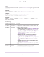 2
2 -
 3
3 -
 4
4 -
 5
5 -
 6
6 -
 7
7 -
8
-
9
-
10
-
11
-
12
-
13
-
14
-
15
-
16
-
17
-
18
-
19
-
20
-
21
-
22
-
23
-
24
-
25
-
26
-
27
-
28
-
29
-
30
-
31
-
32
-
33
-
34
-
35
-
36
-
37
-
38
-
39
-
40
-
41
-
42
-
43
-
44
-
45
-
46
-
47
-
48
-
49
-
50
-
51
-
52
-
53
-
54
-
55
-
56
-
57
-
58
-
59
-
60
-
61
-
62
-
63
-
64
-
65
-
66
-
67
-
68
-
69
-
70
-
71
-
72
-
73
-
74
-
75
-
76
-
77
-
78
-
79
-
80
-
81
-
82
-
83
-
84
-
85
-
86
-
87
-
88
-
89
-
90
-
91
-
92
-
93
-
94
-
95
-
96
-
97
-
98
-
99
-
100
-
101
-
102
-
103
-
104
-
105
-
106
-
107
-
108
-
109
-
110
-
111
-
112
-
113
-
114
-
115
-
116
-
117
-
118
-
119
-
120
-
121
-
122
-
123
-
124
-
125
-
126
-
127
-
128
-
129
-
130
-
131
-
132
-
133
-
134
-
135
-
136
-
137
-
138
-
139
-
140
-
141
-
142
-
143
-
144
-
145
-
146
-
147
-
148
-
149
-
150
-
151
-
152
-
153
-
154
-
155
-
156
-
157
-
158
-
159
-
160
-
161
-
162
-
163
-
164
-
165
-
166
-
167
-
168
-
169
-
170
-
171
-
172
-
173
-
174
-
175
-
176
-
177
-
178
-
179
-
180
-
181
-
182
-
183
-
184
-
185
-
186
-
187
-
188
-
189
-
190
-
191
-
192
-
193
-
194
-
195
-
196
-
197
-
198
-
199
-
200
-
201
-
202
-
203
-
204
-
205
-
206
-
207
-
208
-
209
-
210
-
211
-
212
-
213
-
214
-
215
-
216
-
217
-
218
-
219
-
220
-
221
-
222
-
223
-
224
-
225
-
226
-
227
-
228
-
229
-
230
-
231
-
232
-
233
-
234
-
235
-
236
-
237
-
238
-
239
-
240
-
241
-
242
-
243
-
244
-
245
-
246
-
247
-
248
-
249
-
250
-
251
-
252
-
253
-
254
-
255
-
256
-
257
-
258
-
259
-
260
-
261
-
262
-
263
-
264
-
265
-
266
-
267
-
268
-
269
-
270
-
271
-
272
-
273
-
274
-
275
-
276
-
277
-
278
-
279
-
280
-
281
-
282
-
283
-
284
-
285
-
286
-
287
-
288
-
289
-
290
-
291
-
292
-
293
-
294
-
295
-
296
-
297
-
298
-
299
-
300
-
301
-
302
-
303
-
304
-
305
-
306
-
307
-
308
-
309
-
310
-
311
-
312
-
313
-
314
-
315
-
316
-
317
-
318
-
319
-
320
-
321
-
322
-
323
-
324
-
325
-
326
-
327
-
328
-
329
-
330
-
331
-
332
-
333
-
334
-
335
-
336
-
337
-
338
-
339
-
340
-
341
-
342
-
343
-
344
-
345
-
346
-
347
-
348
-
349
-
350
-
351
-
352
-
353
-
354
-
355
-
356
-
357
-
358
-
359
-
360
-
361
-
362
-
363
-
364
-
365
-
366
-
367
-
368
-
369
-
370
-
371
-
372
-
373
-
374
-
375
-
376
-
377
-
378
-
379
-
380
-
381
-
382
-
383
-
384
-
385
-
386
-
387
-
388
-
389
-
390
-
391
-
392
-
393
-
394
-
395
-
396
-
397
-
398
 |
 |
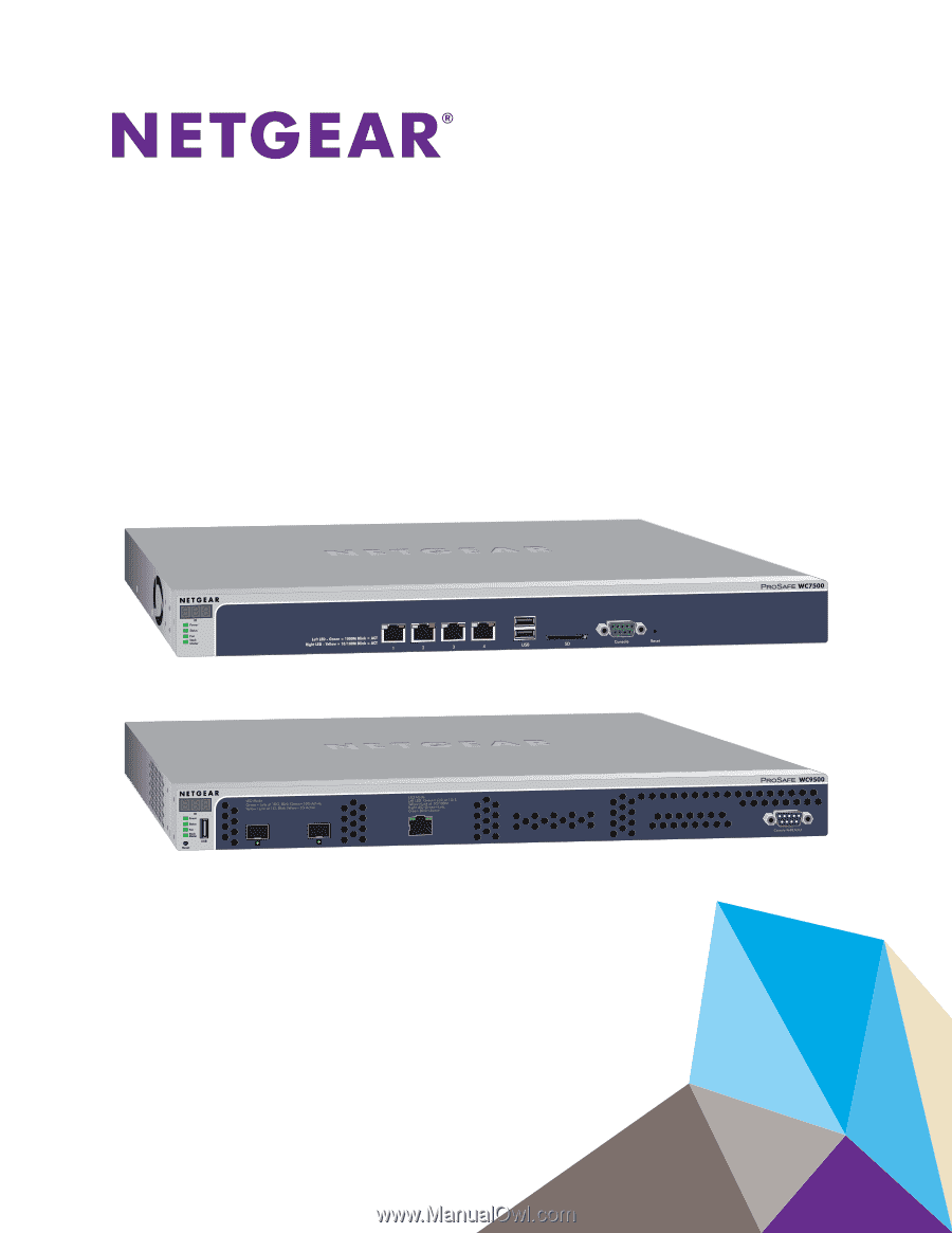
350 East Plumeria Drive
San Jose, CA 95134
USA
November 2016
202-11659-03
ProSAFE Wireless Controller
Models WC7500, WC7600,
WC7600v2, and WC9500
User Manual