Netgear WC7500-Wireless User Manual - Page 71
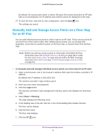
Manually Add and Manage Access Points on a Floor Map for an RF Plan
 |
View all Netgear WC7500-Wireless manuals
Add to My Manuals
Save this manual to your list of manuals |
Page 71 highlights
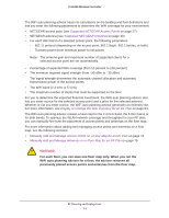
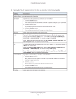
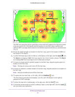
ProSAFE Wireless Controller The WiFi auto planning advisor bases its calculations on the building and floor definitions and lets you enter the following parameters to determine the WiFi coverage for your environment: • NETGEAR access point (see Supported NETGEAR Access Points on page 27) • NETGEAR antenna (see Supported NETGEAR Antennas on page 30) • For each WiFi band of a selected access point, the following parameters: - 802.11 protocol (depending on the access point, 802.11b/g/n, 802.11a/n/ac, or both) - Transmit power (from minimum power to full power) Note: The antenna gain and maximum number of supported clients for a selected access point are set automatically. • Percentage of expected WiFi coverage (from 10 percent to 100 percent) • The minimum required signal strength (from -95 dBm to -30 dBm) The signal strength determines the automatic channel allocation and automatic transmission power of the access points. • The WiFi band (2.4 GHz or 5 GHz) • The maximum number of clients that must be supported on the floor For you to determine the expected financial investment, the WiFi auto planning advisor also lets you enter a price for the selected access point and a price for the selected antenna. Whether or not you enter a price, the WiFi auto planning advisor generates an inventory list. For more information, see Display or Change the WiFi Inventory for an RF Plan on page 84. The WiFi auto planning advisor creates a heat map for the 2.4 GHz band, the 5 GHz band, or for both bands. To optimize the WLAN network coverage and throughput for your RF plan, you can manually fine-tune the placement of access points and antennas on the floor map. For more information about adding and managing access points and antennas on a floor map, see the following sections: • Manually Add and Manage Access Points on a Floor Map for an RF Plan on page 76 • Manually Add and Manage Antennas on a Floor Map for an RF Plan on page 79 WARNING: For each floor, you can save one floor map only. When you run the WiFi auto planning advisor for a floor, the advisor removes all previously placed access points and antennas from the floor map. RF Planning and Deployment 71
-
 1
1 -
2
-
3
-
4
-
5
-
6
-
7
-
8
-
9
-
10
-
11
-
12
-
13
-
14
-
15
-
16
-
17
-
18
-
19
-
20
-
21
-
22
-
23
-
24
-
25
-
26
-
27
-
28
-
29
-
30
-
31
-
32
-
33
-
34
-
35
-
36
-
37
-
38
-
39
-
40
-
41
-
42
-
43
-
44
-
45
-
46
-
47
-
48
-
49
-
50
-
51
-
52
-
53
-
54
-
55
-
56
-
57
-
58
-
59
-
60
-
61
-
62
-
63
-
64
-
65
-
 66
66 -
 67
67 -
 68
68 -
 69
69 -
 70
70 -
 71
71 -
 72
72 -
 73
73 -
 74
74 -
 75
75 -
 76
76 -
77
-
78
-
79
-
80
-
81
-
82
-
83
-
84
-
85
-
86
-
87
-
88
-
89
-
90
-
91
-
92
-
93
-
94
-
95
-
96
-
97
-
98
-
99
-
100
-
101
-
102
-
103
-
104
-
105
-
106
-
107
-
108
-
109
-
110
-
111
-
112
-
113
-
114
-
115
-
116
-
117
-
118
-
119
-
120
-
121
-
122
-
123
-
124
-
125
-
126
-
127
-
128
-
129
-
130
-
131
-
132
-
133
-
134
-
135
-
136
-
137
-
138
-
139
-
140
-
141
-
142
-
143
-
144
-
145
-
146
-
147
-
148
-
149
-
150
-
151
-
152
-
153
-
154
-
155
-
156
-
157
-
158
-
159
-
160
-
161
-
162
-
163
-
164
-
165
-
166
-
167
-
168
-
169
-
170
-
171
-
172
-
173
-
174
-
175
-
176
-
177
-
178
-
179
-
180
-
181
-
182
-
183
-
184
-
185
-
186
-
187
-
188
-
189
-
190
-
191
-
192
-
193
-
194
-
195
-
196
-
197
-
198
-
199
-
200
-
201
-
202
-
203
-
204
-
205
-
206
-
207
-
208
-
209
-
210
-
211
-
212
-
213
-
214
-
215
-
216
-
217
-
218
-
219
-
220
-
221
-
222
-
223
-
224
-
225
-
226
-
227
-
228
-
229
-
230
-
231
-
232
-
233
-
234
-
235
-
236
-
237
-
238
-
239
-
240
-
241
-
242
-
243
-
244
-
245
-
246
-
247
-
248
-
249
-
250
-
251
-
252
-
253
-
254
-
255
-
256
-
257
-
258
-
259
-
260
-
261
-
262
-
263
-
264
-
265
-
266
-
267
-
268
-
269
-
270
-
271
-
272
-
273
-
274
-
275
-
276
-
277
-
278
-
279
-
280
-
281
-
282
-
283
-
284
-
285
-
286
-
287
-
288
-
289
-
290
-
291
-
292
-
293
-
294
-
295
-
296
-
297
-
298
-
299
-
300
-
301
-
302
-
303
-
304
-
305
-
306
-
307
-
308
-
309
-
310
-
311
-
312
-
313
-
314
-
315
-
316
-
317
-
318
-
319
-
320
-
321
-
322
-
323
-
324
-
325
-
326
-
327
-
328
-
329
-
330
-
331
-
332
-
333
-
334
-
335
-
336
-
337
-
338
-
339
-
340
-
341
-
342
-
343
-
344
-
345
-
346
-
347
-
348
-
349
-
350
-
351
-
352
-
353
-
354
-
355
-
356
-
357
-
358
-
359
-
360
-
361
-
362
-
363
-
364
-
365
-
366
-
367
-
368
-
369
-
370
-
371
-
372
-
373
-
374
-
375
-
376
-
377
-
378
-
379
-
380
-
381
-
382
-
383
-
384
-
385
-
386
-
387
-
388
-
389
-
390
-
391
-
392
-
393
-
394
-
395
-
396
-
397
-
398
 |
 |
