Netgear WC7500-Wireless User Manual - Page 83
Display and Recalculate the WiFi Coverage for a Heat Map
 |
View all Netgear WC7500-Wireless manuals
Add to My Manuals
Save this manual to your list of manuals |
Page 83 highlights
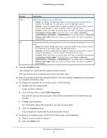
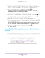
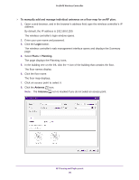
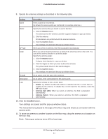
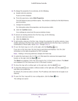
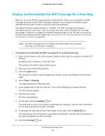
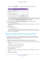
ProSAFE Wireless Controller Display and Recalculate the WiFi Coverage for a Heat Map After you set up an RF plan and generate a heat map for a floor, you can display the WiFi coverage and view how the WiFi coverage changes if you change the minimum signal strength with the same number of access points and antennas. The default minimum signal strength is -62 dBm. The WiFi coverage percentage is calculated based on this value. You can change this value and recalculate the coverage percentage. However, to change the minimum signal strength for an RF plan, you must run the WiFi auto planning advisor again (see Use the WiFi Auto Planning Advisor to Generate an RF Plan for a Floor on page 70). Note: The WiFi coverage tool is for display and information only. However, heat maps can function in realtime. To display and recalculate the WiFi coverage for an existing heat map: 1. Open a web browser, and in the browser's address field, type the wireless controller's IP address. By default, the IP address is 192.168.0.250. The wireless controller's login window opens. 2. Enter your user name and password. 3. Click the Login button. The wireless controller's web management interface opens and displays the Summary page. 4. Select Plans > Planning. The page displays the Planning icons. 5. In the building tree on the left, click the + icon of the building that contains the floor. The floor names display. 6. Click the floor name. The floor map displays. 7. On the right, click the HeatMap icon. The heat map for the 2.4 GHz band is generated and displays. Use the color information on the right as guidance for WiFi coverage. 8. To generate the heat map for the 5 GHz band, on the right, click the Band icon. The heat map for the 5 GHz band is generated and displays. Use the color information on the right as guidance for WiFi coverage. 9. Click the Coverage icon. RF Planning and Deployment 83
-
 1
1 -
2
-
3
-
4
-
5
-
6
-
7
-
8
-
9
-
10
-
11
-
12
-
13
-
14
-
15
-
16
-
17
-
18
-
19
-
20
-
21
-
22
-
23
-
24
-
25
-
26
-
27
-
28
-
29
-
30
-
31
-
32
-
33
-
34
-
35
-
36
-
37
-
38
-
39
-
40
-
41
-
42
-
43
-
44
-
45
-
46
-
47
-
48
-
49
-
50
-
51
-
52
-
53
-
54
-
55
-
56
-
57
-
58
-
59
-
60
-
61
-
62
-
63
-
64
-
65
-
66
-
67
-
68
-
69
-
70
-
71
-
72
-
73
-
74
-
75
-
76
-
77
-
 78
78 -
 79
79 -
 80
80 -
 81
81 -
 82
82 -
 83
83 -
 84
84 -
 85
85 -
 86
86 -
 87
87 -
 88
88 -
89
-
90
-
91
-
92
-
93
-
94
-
95
-
96
-
97
-
98
-
99
-
100
-
101
-
102
-
103
-
104
-
105
-
106
-
107
-
108
-
109
-
110
-
111
-
112
-
113
-
114
-
115
-
116
-
117
-
118
-
119
-
120
-
121
-
122
-
123
-
124
-
125
-
126
-
127
-
128
-
129
-
130
-
131
-
132
-
133
-
134
-
135
-
136
-
137
-
138
-
139
-
140
-
141
-
142
-
143
-
144
-
145
-
146
-
147
-
148
-
149
-
150
-
151
-
152
-
153
-
154
-
155
-
156
-
157
-
158
-
159
-
160
-
161
-
162
-
163
-
164
-
165
-
166
-
167
-
168
-
169
-
170
-
171
-
172
-
173
-
174
-
175
-
176
-
177
-
178
-
179
-
180
-
181
-
182
-
183
-
184
-
185
-
186
-
187
-
188
-
189
-
190
-
191
-
192
-
193
-
194
-
195
-
196
-
197
-
198
-
199
-
200
-
201
-
202
-
203
-
204
-
205
-
206
-
207
-
208
-
209
-
210
-
211
-
212
-
213
-
214
-
215
-
216
-
217
-
218
-
219
-
220
-
221
-
222
-
223
-
224
-
225
-
226
-
227
-
228
-
229
-
230
-
231
-
232
-
233
-
234
-
235
-
236
-
237
-
238
-
239
-
240
-
241
-
242
-
243
-
244
-
245
-
246
-
247
-
248
-
249
-
250
-
251
-
252
-
253
-
254
-
255
-
256
-
257
-
258
-
259
-
260
-
261
-
262
-
263
-
264
-
265
-
266
-
267
-
268
-
269
-
270
-
271
-
272
-
273
-
274
-
275
-
276
-
277
-
278
-
279
-
280
-
281
-
282
-
283
-
284
-
285
-
286
-
287
-
288
-
289
-
290
-
291
-
292
-
293
-
294
-
295
-
296
-
297
-
298
-
299
-
300
-
301
-
302
-
303
-
304
-
305
-
306
-
307
-
308
-
309
-
310
-
311
-
312
-
313
-
314
-
315
-
316
-
317
-
318
-
319
-
320
-
321
-
322
-
323
-
324
-
325
-
326
-
327
-
328
-
329
-
330
-
331
-
332
-
333
-
334
-
335
-
336
-
337
-
338
-
339
-
340
-
341
-
342
-
343
-
344
-
345
-
346
-
347
-
348
-
349
-
350
-
351
-
352
-
353
-
354
-
355
-
356
-
357
-
358
-
359
-
360
-
361
-
362
-
363
-
364
-
365
-
366
-
367
-
368
-
369
-
370
-
371
-
372
-
373
-
374
-
375
-
376
-
377
-
378
-
379
-
380
-
381
-
382
-
383
-
384
-
385
-
386
-
387
-
388
-
389
-
390
-
391
-
392
-
393
-
394
-
395
-
396
-
397
-
398
 |
 |
