Netgear WC7500-Wireless User Manual - Page 23
WC7600 and WC9500 Back Panel Components, Back panel models WC7600 and WC9500, Table 4.
 |
View all Netgear WC7500-Wireless manuals
Add to My Manuals
Save this manual to your list of manuals |
Page 23 highlights
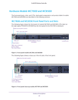
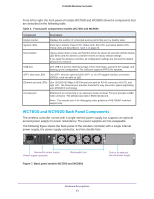
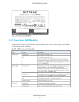
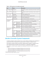
ProSAFE Wireless Controller From left to right, the front panel of models WC7600 and WC9500 show the components that are described in the following table. Table 4. Front panel components models WC7600 and WC9500 Component Description Digital counter Displays the number of connected access points that are in a healthy state. System LEDs From top to bottom: Power LED, Status LED, Fan LED, and Stack Master LED. These LEDs are described in Table 5 on page 25. Reset button Using a sharp object, press and hold this button for about 10 seconds until the Status LED blinks and the wireless controller returns to factory default settings. If you reset the wireless controller, all configuration settings are lost and the default password is restored. USB port One USB 2.0 port for external storage of floor heat maps, saving of the syslogs, and backing up the configuration. The USB port supports FAT32 file systems. SFP+ slots and LEDs Two SFP+ slots for optional 10GE SFP+ or 1G SFP gigabit interface converters (GBICs), each slot with an LED. Ethernet port and LEDs One 10/100/1000 Mbps LAN Ethernet port with an RJ-45 connector, left LED, and right LED. The Ethernet port provides switched N-way, automatic speed negotiating, auto MDI/MDIX technology. Console port RS232 port for connecting to an optional console terminal. The port provides a DB9 male connector. The default baud rate is 9600 bits/second. Note: The console port is for debugging under guidance of NETGEAR technical support only. WC7600 and WC9500 Back Panel Components The wireless controller comes with a single internal power supply but supports an optional second power supply for power redundancy. The power supplies are hot-swappable. The following figure shows the back panel of the wireless controller with a single internal power supply, the power supply connector, and two double fans. Removable power supply Power supply connector Removable fans Figure 7. Back panel models WC7600 and WC9500 Slot for an optional second power supply Hardware Descriptions 23
-
 1
1 -
2
-
3
-
4
-
5
-
6
-
7
-
8
-
9
-
10
-
11
-
12
-
13
-
14
-
15
-
16
-
17
-
 18
18 -
 19
19 -
 20
20 -
 21
21 -
 22
22 -
 23
23 -
 24
24 -
 25
25 -
 26
26 -
 27
27 -
 28
28 -
29
-
30
-
31
-
32
-
33
-
34
-
35
-
36
-
37
-
38
-
39
-
40
-
41
-
42
-
43
-
44
-
45
-
46
-
47
-
48
-
49
-
50
-
51
-
52
-
53
-
54
-
55
-
56
-
57
-
58
-
59
-
60
-
61
-
62
-
63
-
64
-
65
-
66
-
67
-
68
-
69
-
70
-
71
-
72
-
73
-
74
-
75
-
76
-
77
-
78
-
79
-
80
-
81
-
82
-
83
-
84
-
85
-
86
-
87
-
88
-
89
-
90
-
91
-
92
-
93
-
94
-
95
-
96
-
97
-
98
-
99
-
100
-
101
-
102
-
103
-
104
-
105
-
106
-
107
-
108
-
109
-
110
-
111
-
112
-
113
-
114
-
115
-
116
-
117
-
118
-
119
-
120
-
121
-
122
-
123
-
124
-
125
-
126
-
127
-
128
-
129
-
130
-
131
-
132
-
133
-
134
-
135
-
136
-
137
-
138
-
139
-
140
-
141
-
142
-
143
-
144
-
145
-
146
-
147
-
148
-
149
-
150
-
151
-
152
-
153
-
154
-
155
-
156
-
157
-
158
-
159
-
160
-
161
-
162
-
163
-
164
-
165
-
166
-
167
-
168
-
169
-
170
-
171
-
172
-
173
-
174
-
175
-
176
-
177
-
178
-
179
-
180
-
181
-
182
-
183
-
184
-
185
-
186
-
187
-
188
-
189
-
190
-
191
-
192
-
193
-
194
-
195
-
196
-
197
-
198
-
199
-
200
-
201
-
202
-
203
-
204
-
205
-
206
-
207
-
208
-
209
-
210
-
211
-
212
-
213
-
214
-
215
-
216
-
217
-
218
-
219
-
220
-
221
-
222
-
223
-
224
-
225
-
226
-
227
-
228
-
229
-
230
-
231
-
232
-
233
-
234
-
235
-
236
-
237
-
238
-
239
-
240
-
241
-
242
-
243
-
244
-
245
-
246
-
247
-
248
-
249
-
250
-
251
-
252
-
253
-
254
-
255
-
256
-
257
-
258
-
259
-
260
-
261
-
262
-
263
-
264
-
265
-
266
-
267
-
268
-
269
-
270
-
271
-
272
-
273
-
274
-
275
-
276
-
277
-
278
-
279
-
280
-
281
-
282
-
283
-
284
-
285
-
286
-
287
-
288
-
289
-
290
-
291
-
292
-
293
-
294
-
295
-
296
-
297
-
298
-
299
-
300
-
301
-
302
-
303
-
304
-
305
-
306
-
307
-
308
-
309
-
310
-
311
-
312
-
313
-
314
-
315
-
316
-
317
-
318
-
319
-
320
-
321
-
322
-
323
-
324
-
325
-
326
-
327
-
328
-
329
-
330
-
331
-
332
-
333
-
334
-
335
-
336
-
337
-
338
-
339
-
340
-
341
-
342
-
343
-
344
-
345
-
346
-
347
-
348
-
349
-
350
-
351
-
352
-
353
-
354
-
355
-
356
-
357
-
358
-
359
-
360
-
361
-
362
-
363
-
364
-
365
-
366
-
367
-
368
-
369
-
370
-
371
-
372
-
373
-
374
-
375
-
376
-
377
-
378
-
379
-
380
-
381
-
382
-
383
-
384
-
385
-
386
-
387
-
388
-
389
-
390
-
391
-
392
-
393
-
394
-
395
-
396
-
397
-
398
 |
 |
