Dell PowerEdge R750xa EMC Installation and Service Manual - Page 12
Right control panel view, Table 4. Left control panel with optional iDRAC Quick Sync 2 indicator
 |
View all Dell PowerEdge R750xa manuals
Add to My Manuals
Save this manual to your list of manuals |
Page 12 highlights
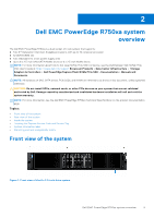
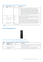
Figure 4. Left control panel with optional iDRAC Quick Sync 2 indicator Table 4. Left control panel with optional iDRAC Quick Sync 2 indicator Item Indicator, button, or connector Icon Description 1 Status LED indicators N/A Indicates the status of the system. For more information, see the Status LED indicators section. 2 System health and system ID indicator Indicates the system health. For more information, see the System health and system ID indicator codes section. 3 iDRAC Quick Sync 2 wireless indicator (optional) Indicates if the iDRAC Quick Sync 2 wireless option is activated. The Quick Sync 2 feature allows management of the system using mobile devices. This feature aggregates hardware/ firmware inventory and various system level diagnostic/error information that can be used in troubleshooting the system. You can access system inventory, Dell Lifecycle Controller logs or system logs, system health status, and also configure iDRAC, BIOS, and networking parameters. You can also launch the virtual Keyboard, Video, and Mouse (KVM) viewer and virtual Kernelbased Virtual Machine (KVM), on a supported mobile device. For more information, see the Integrated Dell Remote Access Controller User's Guide at www.dell.com/poweredgemanuals. NOTE: For more information about the indicator codes, see the System diagnostics and indicator codes section. Right control panel view Figure 5. Right control panel view Table 5. Right control panel Ite Indicator or button m Icon 1 Power button Description Indicates if the system is powered on or off. Press the power button to manually power on or off the system. 12 Dell EMC PowerEdge R750xa system overview
-
 1
1 -
2
-
3
-
4
-
5
-
6
-
 7
7 -
 8
8 -
 9
9 -
 10
10 -
 11
11 -
 12
12 -
 13
13 -
 14
14 -
 15
15 -
 16
16 -
 17
17 -
18
-
19
-
20
-
21
-
22
-
23
-
24
-
25
-
26
-
27
-
28
-
29
-
30
-
31
-
32
-
33
-
34
-
35
-
36
-
37
-
38
-
39
-
40
-
41
-
42
-
43
-
44
-
45
-
46
-
47
-
48
-
49
-
50
-
51
-
52
-
53
-
54
-
55
-
56
-
57
-
58
-
59
-
60
-
61
-
62
-
63
-
64
-
65
-
66
-
67
-
68
-
69
-
70
-
71
-
72
-
73
-
74
-
75
-
76
-
77
-
78
-
79
-
80
-
81
-
82
-
83
-
84
-
85
-
86
-
87
-
88
-
89
-
90
-
91
-
92
-
93
-
94
-
95
-
96
-
97
-
98
-
99
-
100
-
101
-
102
-
103
-
104
-
105
-
106
-
107
-
108
-
109
-
110
-
111
-
112
-
113
-
114
-
115
-
116
-
117
-
118
-
119
-
120
-
121
-
122
-
123
-
124
-
125
-
126
-
127
-
128
-
129
-
130
-
131
-
132
-
133
-
134
-
135
-
136
-
137
-
138
-
139
-
140
-
141
-
142
-
143
-
144
-
145
-
146
-
147
-
148
-
149
-
150
-
151
-
152
-
153
-
154
-
155
-
156
-
157
-
158
-
159
-
160
-
161
-
162
-
163
-
164
-
165
-
166
-
167
-
168
-
169
-
170
-
171
-
172
-
173
-
174
-
175
-
176
-
177
-
178
-
179
-
180
-
181
-
182
-
183
-
184
-
185
-
186
-
187
-
188
-
189
-
190
 |
 |
