Dell PowerEdge R750xa EMC Installation and Service Manual - Page 154
Initializing the TPM 2.0 for users, System board, Removing the system board
 |
View all Dell PowerEdge R750xa manuals
Add to My Manuals
Save this manual to your list of manuals |
Page 154 highlights
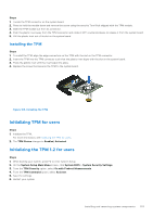
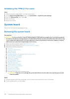
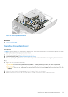
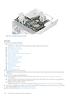
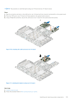
Initializing the TPM 2.0 for users Steps 1. While booting your system, press F2 to enter System Setup. 2. On the System Setup Main Menu screen, click System BIOS > System Security Settings. 3. From the TPM Security option, select On. 4. Save the settings. 5. Restart your system. System board This is a service technician replaceable part only. Removing the system board Prerequisites CAUTION: If you are using the Trusted Platform Module (TPM) with an encryption key, you may be prompted to create a recovery key during program or System Setup. Be sure to create and safely store this recovery key. If you replace this system board, you must supply the recovery key when you restart your system or program before you can access the encrypted data on your drives. 1. Follow the safety guidelines listed in the Safety instructions. 2. Follow the procedure listed in the Before working inside your system. 3. Remove the following components: a. Air shroud b. Cooling fan cage assembly c. Side wall bracket d. Memory modules e. Processor and heat sink module or Liquid cooling module f. BOSS S2 module (if installed) g. Serial COM port (if installed) h. VGA port (if installed) i. R1 and R4 paddle card j. R3 paddle card (If installed) k. Expansion card risers l. IDSDM module (if installed) m. Internal USB card (if installed) n. OCP card (if installed) o. Intrusion switch module p. Power supply units (PSU) q. Disconnect all cables from the system board. CAUTION: Take care not to damage the system identification button while removing the system board from the system. Steps 1. Using the system board holder and plunger, slide the system board towards the front of the system. 2. Lift the system board out of the chassis. 154 Installing and removing system components
-
 1
1 -
2
-
3
-
4
-
5
-
6
-
7
-
8
-
9
-
10
-
11
-
12
-
13
-
14
-
15
-
16
-
17
-
18
-
19
-
20
-
21
-
22
-
23
-
24
-
25
-
26
-
27
-
28
-
29
-
30
-
31
-
32
-
33
-
34
-
35
-
36
-
37
-
38
-
39
-
40
-
41
-
42
-
43
-
44
-
45
-
46
-
47
-
48
-
49
-
50
-
51
-
52
-
53
-
54
-
55
-
56
-
57
-
58
-
59
-
60
-
61
-
62
-
63
-
64
-
65
-
66
-
67
-
68
-
69
-
70
-
71
-
72
-
73
-
74
-
75
-
76
-
77
-
78
-
79
-
80
-
81
-
82
-
83
-
84
-
85
-
86
-
87
-
88
-
89
-
90
-
91
-
92
-
93
-
94
-
95
-
96
-
97
-
98
-
99
-
100
-
101
-
102
-
103
-
104
-
105
-
106
-
107
-
108
-
109
-
110
-
111
-
112
-
113
-
114
-
115
-
116
-
117
-
118
-
119
-
120
-
121
-
122
-
123
-
124
-
125
-
126
-
127
-
128
-
129
-
130
-
131
-
132
-
133
-
134
-
135
-
136
-
137
-
138
-
139
-
140
-
141
-
142
-
143
-
144
-
145
-
146
-
147
-
148
-
 149
149 -
 150
150 -
 151
151 -
 152
152 -
 153
153 -
 154
154 -
 155
155 -
 156
156 -
 157
157 -
 158
158 -
 159
159 -
160
-
161
-
162
-
163
-
164
-
165
-
166
-
167
-
168
-
169
-
170
-
171
-
172
-
173
-
174
-
175
-
176
-
177
-
178
-
179
-
180
-
181
-
182
-
183
-
184
-
185
-
186
-
187
-
188
-
189
-
190
 |
 |
