Dell PowerEdge R750xa EMC Installation and Service Manual - Page 75
Lift up the TIM break lever, Removing the retaining clip
 |
View all Dell PowerEdge R750xa manuals
Add to My Manuals
Save this manual to your list of manuals |
Page 75 highlights
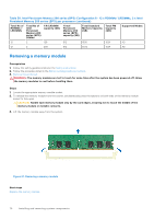
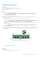
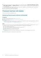
NOTE: Ensure to hold the retaining clip to the heat sink as you lift the TIM break lever. Figure 65. Lift up the TIM break lever 4. Using your thumb and index finger, first hold the retaining clip release tab at the pin 1 connector, pull out the tip of the release tab, and then lift the retaining clip partially from the heat sink. NOTE: Ensure to return the TIM break lever back to its original position. 5. Repeat the above procedure at the remaining three corners of the retaining clip. 6. After all the corners are released from the heat sink, lift the retaining clip from the pin 1 corner of the heat sink. Figure 66. Removing the retaining clip Next steps Replace the processor. Installing and removing system components 75
-
 1
1 -
2
-
3
-
4
-
5
-
6
-
7
-
8
-
9
-
10
-
11
-
12
-
13
-
14
-
15
-
16
-
17
-
18
-
19
-
20
-
21
-
22
-
23
-
24
-
25
-
26
-
27
-
28
-
29
-
30
-
31
-
32
-
33
-
34
-
35
-
36
-
37
-
38
-
39
-
40
-
41
-
42
-
43
-
44
-
45
-
46
-
47
-
48
-
49
-
50
-
51
-
52
-
53
-
54
-
55
-
56
-
57
-
58
-
59
-
60
-
61
-
62
-
63
-
64
-
65
-
66
-
67
-
68
-
69
-
 70
70 -
 71
71 -
 72
72 -
 73
73 -
 74
74 -
 75
75 -
 76
76 -
 77
77 -
 78
78 -
 79
79 -
 80
80 -
81
-
82
-
83
-
84
-
85
-
86
-
87
-
88
-
89
-
90
-
91
-
92
-
93
-
94
-
95
-
96
-
97
-
98
-
99
-
100
-
101
-
102
-
103
-
104
-
105
-
106
-
107
-
108
-
109
-
110
-
111
-
112
-
113
-
114
-
115
-
116
-
117
-
118
-
119
-
120
-
121
-
122
-
123
-
124
-
125
-
126
-
127
-
128
-
129
-
130
-
131
-
132
-
133
-
134
-
135
-
136
-
137
-
138
-
139
-
140
-
141
-
142
-
143
-
144
-
145
-
146
-
147
-
148
-
149
-
150
-
151
-
152
-
153
-
154
-
155
-
156
-
157
-
158
-
159
-
160
-
161
-
162
-
163
-
164
-
165
-
166
-
167
-
168
-
169
-
170
-
171
-
172
-
173
-
174
-
175
-
176
-
177
-
178
-
179
-
180
-
181
-
182
-
183
-
184
-
185
-
186
-
187
-
188
-
189
-
190
 |
 |

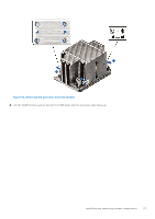
NOTE:
Ensure to hold the retaining clip to the heat sink as you lift the TIM break lever.
Figure 65. Lift up the TIM break lever
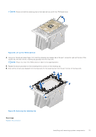
4.
Using your thumb and index finger, first hold the retaining clip release tab at the pin 1 connector, pull out the tip of the
release tab, and then lift the retaining clip partially from the heat sink.
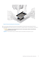
NOTE:
Ensure to return the TIM break lever back to its original position.
5.
Repeat the above procedure at the remaining three corners of the retaining clip.
6.
After all the corners are released from the heat sink, lift the retaining clip from the pin 1 corner of the heat sink.
Figure 66. Removing the retaining clip
Next steps
Replace the processor
.
Installing and removing system components
75