Dell PowerEdge R750xa EMC Installation and Service Manual - Page 72
Processor and heat sink module, Removing the processor and heat sink module
 |
View all Dell PowerEdge R750xa manuals
Add to My Manuals
Save this manual to your list of manuals |
Page 72 highlights
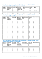
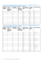
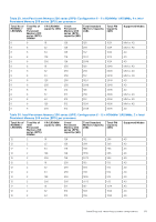
3. To verify if the memory module has been installed properly, press F2 and navigate to System Setup Main Menu > System BIOS > Memory Settings. In the Memory Settings screen, the System Memory Size must reflect the updated capacity of the installed memory. 4. If the System Memory Size is incorrect, one or more of the memory modules may not be installed properly. Ensure that the memory modules are firmly seated in their sockets. 5. Run the system memory test in system diagnostics. Processor and heat sink module This is a service technician replaceable part only. Removing the processor and heat sink module Prerequisites 1. Follow the safety guidelines listed in the Safety instructions. 2. Follow the procedure listed in the Before working inside your system. 3. Remove the air shroud. NOTE: The heat sink and processor are hot to touch for some time after the system has been powered down. Allow the heat sink and processor to cool down before handling them. Steps 1. Ensure all four anti-tilt wires are in the locked position (outward position), and then using a Torx #T30 screwdriver, loosen the captive screws on the processor heat sink module (PHM) in the order that is mentioned below: a. Loosen the first screw three turns. b. Loosen the screw diagonally opposite to the screw you loosened first. c. Repeat the procedure for the remaining two screws. d. Return to the first screw and loosen it completely. NOTE: Ensure that the anti-tilt wires on the PHM are in locked position when loosening the captive screws. 2. Set all the anti-tilt wires to unlocked position (inward position). 72 Installing and removing system components
-
 1
1 -
2
-
3
-
4
-
5
-
6
-
7
-
8
-
9
-
10
-
11
-
12
-
13
-
14
-
15
-
16
-
17
-
18
-
19
-
20
-
21
-
22
-
23
-
24
-
25
-
26
-
27
-
28
-
29
-
30
-
31
-
32
-
33
-
34
-
35
-
36
-
37
-
38
-
39
-
40
-
41
-
42
-
43
-
44
-
45
-
46
-
47
-
48
-
49
-
50
-
51
-
52
-
53
-
54
-
55
-
56
-
57
-
58
-
59
-
60
-
61
-
62
-
63
-
64
-
65
-
66
-
 67
67 -
 68
68 -
 69
69 -
 70
70 -
 71
71 -
 72
72 -
 73
73 -
 74
74 -
 75
75 -
 76
76 -
 77
77 -
78
-
79
-
80
-
81
-
82
-
83
-
84
-
85
-
86
-
87
-
88
-
89
-
90
-
91
-
92
-
93
-
94
-
95
-
96
-
97
-
98
-
99
-
100
-
101
-
102
-
103
-
104
-
105
-
106
-
107
-
108
-
109
-
110
-
111
-
112
-
113
-
114
-
115
-
116
-
117
-
118
-
119
-
120
-
121
-
122
-
123
-
124
-
125
-
126
-
127
-
128
-
129
-
130
-
131
-
132
-
133
-
134
-
135
-
136
-
137
-
138
-
139
-
140
-
141
-
142
-
143
-
144
-
145
-
146
-
147
-
148
-
149
-
150
-
151
-
152
-
153
-
154
-
155
-
156
-
157
-
158
-
159
-
160
-
161
-
162
-
163
-
164
-
165
-
166
-
167
-
168
-
169
-
170
-
171
-
172
-
173
-
174
-
175
-
176
-
177
-
178
-
179
-
180
-
181
-
182
-
183
-
184
-
185
-
186
-
187
-
188
-
189
-
190
 |
 |