Dell PowerEdge R750xa EMC Installation and Service Manual - Page 65
Intel Persistent Memory 200 series (BPS) installation guidelines, Processor, Configuration
 |
View all Dell PowerEdge R750xa manuals
Add to My Manuals
Save this manual to your list of manuals |
Page 65 highlights
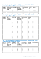
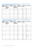
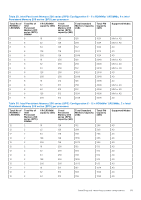
Table 23. Memory population rules (continued) Processor Configuration Memory population Memory population information and processor 2 population should match) B{8}, A{9}, B{9}, A{10}, B{10}, A{11}, B{11}, A{12}, B{12}, A{13}, B{13}, A{14}, B{14}, A{15}, B{15}, A{16}, B{16} NOTE: Optimizer population order is not traditional for 8 and 16 DIMMs installations for dual processor. ● Populate all the sockets with white release tabs first, followed by the black release tabs. ● Memory modules of different capacities can be mixed provided other memory population rules are followed. NOTE: For example, 8 GB and 16 GB memory modules can be mixed. ● Mixing of more than two memory module capacities in a system is not supported. ● Unbalanced or odd memory configuration results in a performance loss and system may not identify the memory modules being installed, so always populate memory channels identically with equal DIMMs for best performance. ● Supported RDIMM / LRDIMM configurations are 1, 2, 4, 6, 8, 12, or 16 DIMMs per processor. Intel Persistent Memory 200 series (BPS) installation guidelines The following are the recommended guidelines for installing Intel Persistent Memory 200 series (BPS) memory modules: ● Each system supports maximum of one Intel Persistent Memory 200 series (BPS) memory module per channel. NOTE: If two different Intel Persistent Memory 200 series (BPS) capacities are mixed, an F1/F2 warning is displayed as the configuration is not supported. ● Intel Persistent Memory 200 series (BPS) can be mixed with RDIMM, LRDIMM, and 3DS LRDIMM. ● Mixing of DDR4 DIMM types (RDIMM, LRDIMM, and 3DS LRDIMM), within channels, for Integrated Memory Controller (iMC), or across sockets are not supported. ● Mixing of Intel Persistent Memory 200 series (BPS) operating modes (App Direct Mode, Memory Mode) is not supported. ● If only one DIMM is populated on a channel, then the DIMM should always be populated in the first slot in that channel (white slot). ● If a Intel Persistent Memory 200 series (BPS) and a DDR4 DIMM are populated on the same channel, always plug Intel Persistent Memory 200 series (BPS) on second slot (black slot). ● If the Intel Persistent Memory 200 series (BPS) is configured in Memory Mode, the recommended DDR4 to Intel Persistent Memory 200 series (BPS) capacity ratio is 1:4 to 1:16 per iMC. ● Intel Persistent Memory 200 series (BPS) cannot be mixed with other capacities of Intel Persistent Memory 200 series (BPS) or with NVDIMMs. ● Mixing different capacities of RDIMMs and LRDIMMs are not allowed when Intel Persistent Memory 200 series (BPS) is installed. ● Intel Persistent Memory 200 series (BPS) of different capacities are not allowed. ● VMware ESXi boot takes longer time when higher capacity of Intel Persistent Memory 200 series (BPS) are configured in App Direct Mode, This is Address Range Scrub (ARS). This is expected as background Address Range Scrub (ARS) is going on the interleave sets and needs to be completed prior the pMem datastore is mounted on ESXi. ● In App Direct Mode (AP), sockets can be populated symmetrically or asymmetrically. ● In Memory Mode (MM), sockets can be populated symmetrically. ● Memory mode is not supported for the 6+1, 8+1 and 12+2 configurations irrespective of DDR to Intel Persistent Memory 200 series (BPS) capacity ratio. ● In VMware ESXI environment, if BPS goal is changed between App Direct Mode and Memory Mode, it is recommended to sanitize the Intel Persistent Memory 200 series (BPS) before creating a new goal. ● Populate Intel Persistent Memory 200 series (BPS) in DIMM slot 1, unless Intel Persistent Memory 200 series (BPS) is the only DIMM in that channel, and then populate in DIMM slot 0. For more information about the supported Intel Persistent Memory 200 series (BPS) configurations, see the Dell EMC Intel Persistent Memory 200 series (BPS) User's Guide at https://www.dell.com/support/home/products/server_int/ server_int_poweredge. Installing and removing system components 65
-
 1
1 -
2
-
3
-
4
-
5
-
6
-
7
-
8
-
9
-
10
-
11
-
12
-
13
-
14
-
15
-
16
-
17
-
18
-
19
-
20
-
21
-
22
-
23
-
24
-
25
-
26
-
27
-
28
-
29
-
30
-
31
-
32
-
33
-
34
-
35
-
36
-
37
-
38
-
39
-
40
-
41
-
42
-
43
-
44
-
45
-
46
-
47
-
48
-
49
-
50
-
51
-
52
-
53
-
54
-
55
-
56
-
57
-
58
-
59
-
 60
60 -
 61
61 -
 62
62 -
 63
63 -
 64
64 -
 65
65 -
 66
66 -
 67
67 -
 68
68 -
 69
69 -
 70
70 -
71
-
72
-
73
-
74
-
75
-
76
-
77
-
78
-
79
-
80
-
81
-
82
-
83
-
84
-
85
-
86
-
87
-
88
-
89
-
90
-
91
-
92
-
93
-
94
-
95
-
96
-
97
-
98
-
99
-
100
-
101
-
102
-
103
-
104
-
105
-
106
-
107
-
108
-
109
-
110
-
111
-
112
-
113
-
114
-
115
-
116
-
117
-
118
-
119
-
120
-
121
-
122
-
123
-
124
-
125
-
126
-
127
-
128
-
129
-
130
-
131
-
132
-
133
-
134
-
135
-
136
-
137
-
138
-
139
-
140
-
141
-
142
-
143
-
144
-
145
-
146
-
147
-
148
-
149
-
150
-
151
-
152
-
153
-
154
-
155
-
156
-
157
-
158
-
159
-
160
-
161
-
162
-
163
-
164
-
165
-
166
-
167
-
168
-
169
-
170
-
171
-
172
-
173
-
174
-
175
-
176
-
177
-
178
-
179
-
180
-
181
-
182
-
183
-
184
-
185
-
186
-
187
-
188
-
189
-
190
 |
 |
