Dell PowerEdge R750xa EMC Installation and Service Manual - Page 64
General memory module installation guidelines, Table 21. Memory channels continued
 |
View all Dell PowerEdge R750xa manuals
Add to My Manuals
Save this manual to your list of manuals |
Page 64 highlights
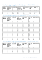
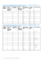
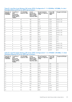
Table 21. Memory channels (continued) Processor Channel Channel Channel C A B Processor Slots B1 Slots B5 2 and B9 and B13 Slots B3 and B11 Channel D Slots B7 and B15 Channel E Slots B2 and B10 Channel F Slots B6 and B14 Channel G Slots B4 and B12 Channel H Slots B8 and B16 Table 22. Supported memory matrix DIMM type Rank Capacity RDIMM 1 R 2 R LRDIMM 4 R Intel persistent 2R memory (BPS) 8 GB 16 GB, 32 GB, 64 GB 128 GB 128 GB, 256 GB, 512 GB DIMM rated voltage and speed Operating Speed 1 DIMM per channel (DPC) DDR4 (1.2 V), 3200 3200 MT/s MT/s DDR4 (1.2 V), 3200 3200 MT/s MT/s DDR4 (1.2 V), 3200 3200 MT/s MT/s DDR4 (1.2 V), 3200 3200 MT/s MT/s 2 DIMMs per channel (DPC) 3200 MT/s 3200 MT/s 3200 MT/s 3200 MT/s General memory module installation guidelines To ensure optimal performance of your system, observe the following general guidelines when configuring your system memory. If your system's memory configurations fail to observe these guidelines, your system might not boot, stop responding during memory configuration, or operate with reduced memory. The memory bus may operate at speeds of 3200 MT/s, 2933 MT/s depending on the following factors: ● System profile selected (for example, Performance Optimized, or Custom [can be run at high speed or lower]) ● Maximum supported DIMM speed of the processors ● Maximum supported speed of the DIMMs NOTE: MT/s indicates DIMM speed in MegaTransfers per second. NOTE: Fault Resilient Memory-Non Uniform Memory Access is supported. The system supports Flexible Memory Configuration, enabling the system to be configured and run in any valid chipset architectural configuration. The following are the recommended guidelines for installing memory modules: ● All DIMMs must be DDR4. ● x4 and x8 DRAM based memory modules can be mixed. ● If memory modules with different speeds are installed, they operate at the speed of the slowest installed memory module(s). ● Populate memory module sockets only if a processor is installed. ○ For single-processor systems, sockets A1 to A16 are available. ○ For dual-processor systems, sockets A1 to A16 and sockets B1 to B16 are available. ● In Optimizer Mode, the DRAM controllers operate independently in the 64-bit mode and provide optimized memory performance. Table 23. Memory population rules Processor Configuration Single processor Optimizer (Independent channel) population order Dual processor (Start with processor1. Processor 1 Optimizer (Independent channel) population order Memory population Memory population information A{1}, A{2}, A{3}, A{4}, A{5}, A{6}, A{7}, A{8}, A{9}, A{10}, A{11}, A{12}, A{13}, A{14}, A{15}, A{16} 1, 2, 4, 6, 8, 12 or 16 DIMMs are allowed. A{1}, B{1}, A{2}, B{2}, A{3}, 2, 4, 8, 12, 16, 24 and 32 B{3}, A{4}, B{4}, A{5}, B{5}, DIMMs are supported per A{6}, B{6}, A{7}, B{7} A{8}, system. 64 Installing and removing system components
-
 1
1 -
2
-
3
-
4
-
5
-
6
-
7
-
8
-
9
-
10
-
11
-
12
-
13
-
14
-
15
-
16
-
17
-
18
-
19
-
20
-
21
-
22
-
23
-
24
-
25
-
26
-
27
-
28
-
29
-
30
-
31
-
32
-
33
-
34
-
35
-
36
-
37
-
38
-
39
-
40
-
41
-
42
-
43
-
44
-
45
-
46
-
47
-
48
-
49
-
50
-
51
-
52
-
53
-
54
-
55
-
56
-
57
-
58
-
 59
59 -
 60
60 -
 61
61 -
 62
62 -
 63
63 -
 64
64 -
 65
65 -
 66
66 -
 67
67 -
 68
68 -
 69
69 -
70
-
71
-
72
-
73
-
74
-
75
-
76
-
77
-
78
-
79
-
80
-
81
-
82
-
83
-
84
-
85
-
86
-
87
-
88
-
89
-
90
-
91
-
92
-
93
-
94
-
95
-
96
-
97
-
98
-
99
-
100
-
101
-
102
-
103
-
104
-
105
-
106
-
107
-
108
-
109
-
110
-
111
-
112
-
113
-
114
-
115
-
116
-
117
-
118
-
119
-
120
-
121
-
122
-
123
-
124
-
125
-
126
-
127
-
128
-
129
-
130
-
131
-
132
-
133
-
134
-
135
-
136
-
137
-
138
-
139
-
140
-
141
-
142
-
143
-
144
-
145
-
146
-
147
-
148
-
149
-
150
-
151
-
152
-
153
-
154
-
155
-
156
-
157
-
158
-
159
-
160
-
161
-
162
-
163
-
164
-
165
-
166
-
167
-
168
-
169
-
170
-
171
-
172
-
173
-
174
-
175
-
176
-
177
-
178
-
179
-
180
-
181
-
182
-
183
-
184
-
185
-
186
-
187
-
188
-
189
-
190
 |
 |
