Garmin GNC 420W Pilots Guide - Page 143
Nearest Flight Service Station (FSS) Quickly tuning an FSS's frequency from the, right
 |
View all Garmin GNC 420W manuals
Add to My Manuals
Save this manual to your list of manuals |
Page 143 highlights
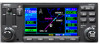
SECTION 8 NRST PAGES 8.8 Nearest Flight Service Station (FSS) Page The Nearest Flight Service Station Page (Figure 8-23) displays the facility name, bearing to, and distance to the five nearest FSS points of communication (within 200 nm of the present position). For each FSS listed, the Nearest Flight Service Station Page also indicates one or more frequencies and may be used to quickly tune the COM transceiver to the FSS's frequency. The selected frequency is placed in the standby field of the COM Window and activated using the COM Flip-flop Key. For duplex operations, 'RX' and 'TX' indications appears beside the listed frequencies, indicating 'receive only' or 'transmit only' frequencies. The associated VOR is also provided for reference. VOR Identifier (For FSS Name Bearing To and Duplex Operation) Distance To Frequency(ies) Position of Current Page within Current Page Group Current Page Group Number of Pages in Current Page Group Figure 8-23 Nearest FSS Page Quickly tuning an FSS's frequency from the Nearest Flight Service Station Page: 1) Select the Nearest Flight Service Station Page, using the steps outlined in Section 8.1 (Figure 8-23). 2) Press the small right knob to activate the cursor. 3) Turn the small right knob to scroll through the list, selecting the desired FSS (Figure 8-24). Figure 8-24 FSS Field Selected 4) Turn the large right knob to scroll down the page (Figure 8-25), highlighting the desired frequency (COM frequency[ies] or VOR frequency for duplex operation). Figure 8-25 Frequency Field Highlighted 190-00140-20 Rev. K GNC 420(A) Pilot's Guide and Reference 8-9
-
 1
1 -
2
-
3
-
4
-
5
-
6
-
7
-
8
-
9
-
10
-
11
-
12
-
13
-
14
-
15
-
16
-
17
-
18
-
19
-
20
-
21
-
22
-
23
-
24
-
25
-
26
-
27
-
28
-
29
-
30
-
31
-
32
-
33
-
34
-
35
-
36
-
37
-
38
-
39
-
40
-
41
-
42
-
43
-
44
-
45
-
46
-
47
-
48
-
49
-
50
-
51
-
52
-
53
-
54
-
55
-
56
-
57
-
58
-
59
-
60
-
61
-
62
-
63
-
64
-
65
-
66
-
67
-
68
-
69
-
70
-
71
-
72
-
73
-
74
-
75
-
76
-
77
-
78
-
79
-
80
-
81
-
82
-
83
-
84
-
85
-
86
-
87
-
88
-
89
-
90
-
91
-
92
-
93
-
94
-
95
-
96
-
97
-
98
-
99
-
100
-
101
-
102
-
103
-
104
-
105
-
106
-
107
-
108
-
109
-
110
-
111
-
112
-
113
-
114
-
115
-
116
-
117
-
118
-
119
-
120
-
121
-
122
-
123
-
124
-
125
-
126
-
127
-
128
-
129
-
130
-
131
-
132
-
133
-
134
-
135
-
136
-
137
-
 138
138 -
 139
139 -
 140
140 -
 141
141 -
 142
142 -
 143
143 -
 144
144 -
 145
145 -
 146
146 -
 147
147 -
 148
148 -
149
-
150
-
151
-
152
-
153
-
154
-
155
-
156
-
157
-
158
-
159
-
160
-
161
-
162
-
163
-
164
-
165
-
166
-
167
-
168
-
169
-
170
-
171
-
172
-
173
-
174
-
175
-
176
-
177
-
178
-
179
-
180
-
181
-
182
-
183
-
184
-
185
-
186
-
187
-
188
-
189
-
190
-
191
-
192
-
193
-
194
-
195
-
196
-
197
-
198
-
199
-
200
-
201
-
202
-
203
-
204
-
205
-
206
-
207
-
208
-
209
-
210
-
211
-
212
-
213
-
214
-
215
-
216
-
217
-
218
-
219
-
220
-
221
-
222
-
223
-
224
-
225
-
226
-
227
-
228
-
229
-
230
-
231
-
232
-
233
-
234
-
235
-
236
-
237
-
238
-
239
-
240
-
241
-
242
-
243
-
244
-
245
-
246
-
247
-
248
-
249
-
250
-
251
-
252
-
253
-
254
-
255
-
256
-
257
-
258
 |
 |
