Garmin GPS 152 Owner's Manual - Page 92
ush mount the GPS 152 unit, ush mount the International version GPS 152 unit - external antenna
 |
UPC - 753759028145
View all Garmin GPS 152 manuals
Add to My Manuals
Save this manual to your list of manuals |
Page 92 highlights
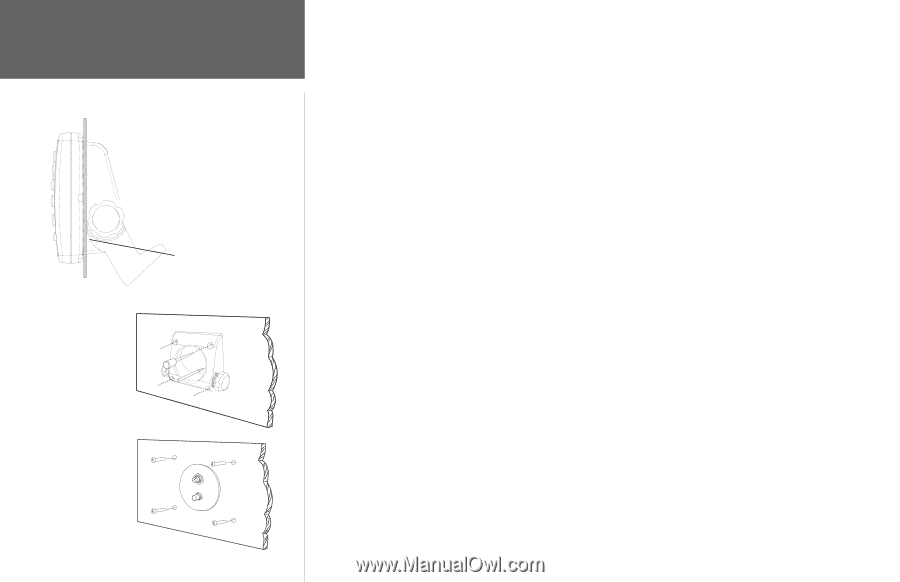
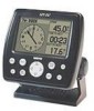
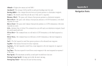
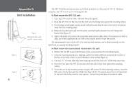
Appendix G Unit Installation Figure 1 Pull bracket down until cam lobe contacts surface. Figure 2 Figure 3 82 The GPS 152 with external antenna can be flush mounted on a flat panel of .08-.52" thickness using the cam lobe feature on its mounting bracket To flush mount the GPS 152 unit: 1. Cut a 4.25"W x 4.25"H (108 x 108 mm) hole in the panel. 2. Place the GPS 152 into the hole from the front until the flange rests against the mounting surface. 3. From the back of the panel, loosely attach the bracket such that the slot in the ratchet area points away from the mounting panel. 4. Rotate the bracket downward until the panel is pinched tightly between the unit's flange and bracket lobe (figure 1). 5. Tighten the knobs and connect the power/data and antenna cables. Note: if the panel is too thick to allow use of the supplied knobs, two M6 screws may be used to secure the bracket. The International version of the GPS 152, with external antenna, can be flush mounted on a flat panel with its existing mounting bracket. To flush mount the International version GPS 152 unit: 1. Remove the four M5 screws from the back of the unit and remove the mounting bracket. 2. Using the mounting bracket as a template, outline the center relief hole and mark the location of the four screw holes centers on your bulkhead or other surface (figure 2). 3. Cut the 2.75" (70 mm) relief hole from the panel and drill the four 0.20" (5.08 mm) screw holes. 4. From the front, place the GPS 152 into the relief hole until it rests flush against the mounting surface. 5. Secure the unit to the mounting surface using the M5 screws. For thick mounting surfaces, insert the M5 screws directly thorough the drilled holes (figure 3). For thin panels, place the mounting bracket on the back side of the panel for more support. Connect the power/data and antenna cables.
-
 1
1 -
2
-
3
-
4
-
5
-
6
-
7
-
8
-
9
-
10
-
11
-
12
-
13
-
14
-
15
-
16
-
17
-
18
-
19
-
20
-
21
-
22
-
23
-
24
-
25
-
26
-
27
-
28
-
29
-
30
-
31
-
32
-
33
-
34
-
35
-
36
-
37
-
38
-
39
-
40
-
41
-
42
-
43
-
44
-
45
-
46
-
47
-
48
-
49
-
50
-
51
-
52
-
53
-
54
-
55
-
56
-
57
-
58
-
59
-
60
-
61
-
62
-
63
-
64
-
65
-
66
-
67
-
68
-
69
-
70
-
71
-
72
-
73
-
74
-
75
-
76
-
77
-
78
-
79
-
80
-
81
-
82
-
83
-
84
-
85
-
86
-
 87
87 -
 88
88 -
 89
89 -
 90
90 -
 91
91 -
 92
92 -
 93
93 -
 94
94 -
 95
95 -
 96
96 -
 97
97 -
98
 |
 |