HP 6125XLG R2306-HP 6125XLG Blade Switch Network Management and Monitoring Con - Page 11
Configuration procedure, System debugging
 |
View all HP 6125XLG manuals
Add to My Manuals
Save this manual to your list of manuals |
Page 11 highlights
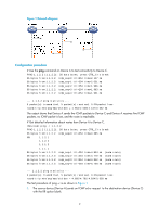
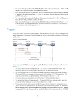
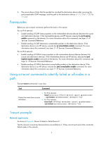
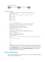
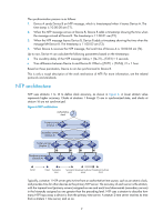
Figure 3 Network diagram 1.1.1.1/24 1.1.1.2/24 1.1.2.1/24 Device A Device B 1.1.2.2/24 Device C Configuration procedure 1. Use the ping command to test connectivity between Device A and Device C. ping 1.1.2.2 PING 1.1.2.2(1.1.2.2): 56 -data bytes, press CTRL_C to break Request time out Request time out Request time out Request time out Request time out --- 1.1.2.2 ping statistics --5 packet(s) transmitted,0 packet(s) received,100.0% packet loss The output shows that Device A and Device C cannot reach each other. 2. Use the tracert command to identify failed nodes: # Enable sending of ICMP timeout packets on Device B. system-view [DeviceB] ip ttl-expires enable # Enable sending of ICMP destination unreachable packets on Device C. system-view [DeviceC] ip unreachables enable # Execute the tracert command on Device A. tracert 1.1.2.2 traceroute to 1.1.2.2(1.1.2.2) 30 hops at most,40 bytes each packet, press CTRL_C to break 1 1.1.1.2 14 ms 10 ms 20 ms 2 *** 3 *** 4 *** 5 The output shows that Device A and Device C cannot reach each other, Device A and Device B can reach each other, and an error has occurred on the connection between Device B and Device C. 3. Use the debugging ip icmp command on Device A and Device C to verify that they can send and receive the specific ICMP packets, or use the display ip routing-table command to verify the connectivity between Device A and Device C. System debugging The device supports debugging for the majority of protocols and features and provides debugging information to help users diagnose errors. 5
-
 1
1 -
2
-
3
-
4
-
5
-
 6
6 -
 7
7 -
 8
8 -
 9
9 -
 10
10 -
 11
11 -
 12
12 -
 13
13 -
 14
14 -
 15
15 -
 16
16 -
17
-
18
-
19
-
20
-
21
-
22
-
23
-
24
-
25
-
26
-
27
-
28
-
29
-
30
-
31
-
32
-
33
-
34
-
35
-
36
-
37
-
38
-
39
-
40
-
41
-
42
-
43
-
44
-
45
-
46
-
47
-
48
-
49
-
50
-
51
-
52
-
53
-
54
-
55
-
56
-
57
-
58
-
59
-
60
-
61
-
62
-
63
-
64
-
65
-
66
-
67
-
68
-
69
-
70
-
71
-
72
-
73
-
74
-
75
-
76
-
77
-
78
-
79
-
80
-
81
-
82
-
83
-
84
-
85
-
86
-
87
-
88
-
89
-
90
-
91
-
92
-
93
-
94
-
95
-
96
-
97
-
98
-
99
-
100
-
101
-
102
-
103
-
104
-
105
-
106
-
107
-
108
-
109
-
110
-
111
-
112
-
113
-
114
-
115
-
116
-
117
-
118
-
119
-
120
-
121
-
122
-
123
-
124
-
125
-
126
-
127
-
128
-
129
-
130
-
131
-
132
-
133
-
134
-
135
-
136
-
137
-
138
-
139
-
140
-
141
-
142
-
143
-
144
-
145
-
146
-
147
-
148
 |
 |