HP 6125XLG R2306-HP 6125XLG Blade Switch Network Management and Monitoring Con - Page 34
NTP client/server mode configuration example, Network requirements, Configuration procedure
 |
View all HP 6125XLG manuals
Add to My Manuals
Save this manual to your list of manuals |
Page 34 highlights
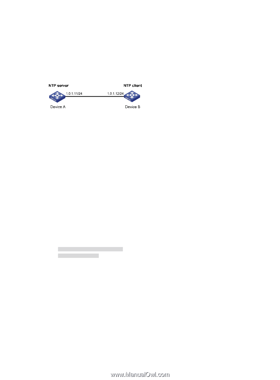
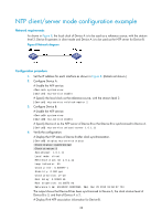
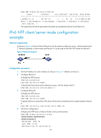
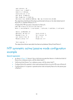
NTP client/server mode configuration example Network requirements As shown in Figure 8, the local clock of Device A is to be used as a reference source, with the stratum level 2. Device B operates in client mode and Device A is to be used as the NTP server for Device B. Figure 8 Network diagram Configuration procedure 1. Set the IP address for each interface as shown in Figure 8. (Details not shown.) 2. Configure Device A: # Enable the NTP service. system-view [DeviceA] ntp-service enable # Specify the local clock as the reference source, with the stratum level 2. [DeviceA] ntp-service refclock-master 2 3. Configure Device B: # Enable the NTP service. system-view [DeviceB] ntp-service enable # Specify Device A as the NTP server of Device B so that Device B is synchronized to Device A. [DeviceB] ntp-service unicast-server 1.0.1.11 4. Verify the configuration: # Display the NTP status of Device B after clock synchronization. [DeviceB] display ntp-service status Clock status: synchronized Clock stratum: 3 System peer: 1.0.1.11 Local mode: client Reference clock ID: 1.0.1.11 Leap indicator: 00 Clock jitter: 0.000977 s Stability: 0.000 pps Clock precision: 2^-10 Root delay: 0.00383 ms Root dispersion: 16.26572 ms Reference time: d0c6033f.b9923965 Wed, Dec 29 2010 18:58:07.724 The output shows that Device B has been synchronized to Device A, the clock stratum level of Device B is 3, and that of Device A is 2. # Display IPv4 NTP association information for Device B. 28
-
 1
1 -
2
-
3
-
4
-
5
-
6
-
7
-
8
-
9
-
10
-
11
-
12
-
13
-
14
-
15
-
16
-
17
-
18
-
19
-
20
-
21
-
22
-
23
-
24
-
25
-
26
-
27
-
28
-
 29
29 -
 30
30 -
 31
31 -
 32
32 -
 33
33 -
 34
34 -
 35
35 -
 36
36 -
 37
37 -
 38
38 -
 39
39 -
40
-
41
-
42
-
43
-
44
-
45
-
46
-
47
-
48
-
49
-
50
-
51
-
52
-
53
-
54
-
55
-
56
-
57
-
58
-
59
-
60
-
61
-
62
-
63
-
64
-
65
-
66
-
67
-
68
-
69
-
70
-
71
-
72
-
73
-
74
-
75
-
76
-
77
-
78
-
79
-
80
-
81
-
82
-
83
-
84
-
85
-
86
-
87
-
88
-
89
-
90
-
91
-
92
-
93
-
94
-
95
-
96
-
97
-
98
-
99
-
100
-
101
-
102
-
103
-
104
-
105
-
106
-
107
-
108
-
109
-
110
-
111
-
112
-
113
-
114
-
115
-
116
-
117
-
118
-
119
-
120
-
121
-
122
-
123
-
124
-
125
-
126
-
127
-
128
-
129
-
130
-
131
-
132
-
133
-
134
-
135
-
136
-
137
-
138
-
139
-
140
-
141
-
142
-
143
-
144
-
145
-
146
-
147
-
148
 |
 |