HP 6125XLG R2306-HP 6125XLG Blade Switch Network Management and Monitoring Con - Page 51
Network diagram
 |
View all HP 6125XLG manuals
Add to My Manuals
Save this manual to your list of manuals |
Page 51 highlights
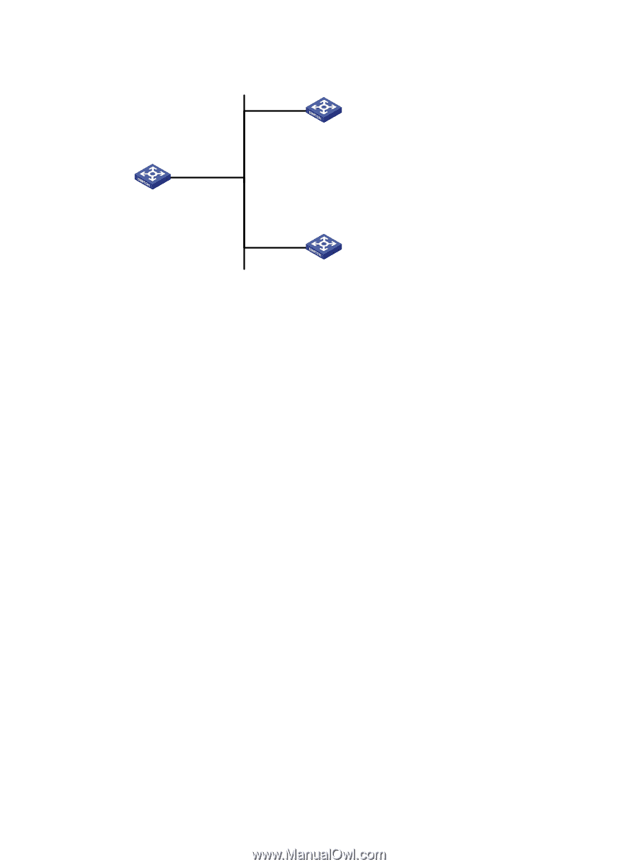
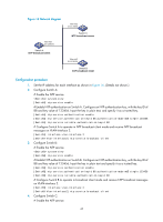
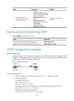
Figure 16 Network diagram Vlan-int2 3.0.1.30/24 Switch A NTP broadcast client Vlan-int2 3.0.1.31/24 Switch C NTP broadcast server Vlan-int2 3.0.1.32/24 Switch B NTP broadcast client Configuration procedure 1. Set the IP address for each interface as shown in Figure 16. (Details not shown.) 2. Configure Switch A: # Enable the NTP service. system-view [SwitchA] ntp-service enable # Enable NTP authentication on Switch A. Configure an NTP authentication key, with the key ID of 88 and key value of 123456. Input the key in plain text, and specify it as a trusted key. [SwitchA] ntp-service authentication enable [SwitchA] ntp-service authentication-keyid 88 authentication-mode md5 simple 123456 [SwitchA] ntp-service reliable authentication-keyid 88 # Configure Switch A to operate in NTP broadcast client mode and receive NTP broadcast messages on VLAN-interface 2. [SwitchA] interface vlan-interface 2 [SwitchA-Vlan-interface2] ntp-service broadcast-client 3. Configure Switch B: # Enable the NTP service. system-view [SwitchB] ntp-service enable # Enable NTP authentication on Switch B. Configure an NTP authentication key, with the key ID of 88 and key value of 123456. Input the key in plain text and specify it as a trusted key. [SwitchB] ntp-service authentication enable [SwitchB] ntp-service authentication-keyid 88 authentication-mode md5 simple 123456 [SwitchB] ntp-service reliable authentication-keyid 88 # Configure Switch B to operate in broadcast client mode and receive NTP broadcast messages on VLAN-interface 2. [SwitchB] interface vlan-interface 2 [SwitchB-Vlan-interface2] ntp-service broadcast-client 4. Configure Switch C: # Enable the NTP service. 45
-
 1
1 -
2
-
3
-
4
-
5
-
6
-
7
-
8
-
9
-
10
-
11
-
12
-
13
-
14
-
15
-
16
-
17
-
18
-
19
-
20
-
21
-
22
-
23
-
24
-
25
-
26
-
27
-
28
-
29
-
30
-
31
-
32
-
33
-
34
-
35
-
36
-
37
-
38
-
39
-
40
-
41
-
42
-
43
-
44
-
45
-
 46
46 -
 47
47 -
 48
48 -
 49
49 -
 50
50 -
 51
51 -
 52
52 -
 53
53 -
 54
54 -
 55
55 -
 56
56 -
57
-
58
-
59
-
60
-
61
-
62
-
63
-
64
-
65
-
66
-
67
-
68
-
69
-
70
-
71
-
72
-
73
-
74
-
75
-
76
-
77
-
78
-
79
-
80
-
81
-
82
-
83
-
84
-
85
-
86
-
87
-
88
-
89
-
90
-
91
-
92
-
93
-
94
-
95
-
96
-
97
-
98
-
99
-
100
-
101
-
102
-
103
-
104
-
105
-
106
-
107
-
108
-
109
-
110
-
111
-
112
-
113
-
114
-
115
-
116
-
117
-
118
-
119
-
120
-
121
-
122
-
123
-
124
-
125
-
126
-
127
-
128
-
129
-
130
-
131
-
132
-
133
-
134
-
135
-
136
-
137
-
138
-
139
-
140
-
141
-
142
-
143
-
144
-
145
-
146
-
147
-
148
 |
 |