HP 6125XLG R2306-HP 6125XLG Blade Switch Network Management and Monitoring Con - Page 123
Layer 2 remote port mirroring configuration example, Network requirements, Configuration procedure
 |
View all HP 6125XLG manuals
Add to My Manuals
Save this manual to your list of manuals |
Page 123 highlights
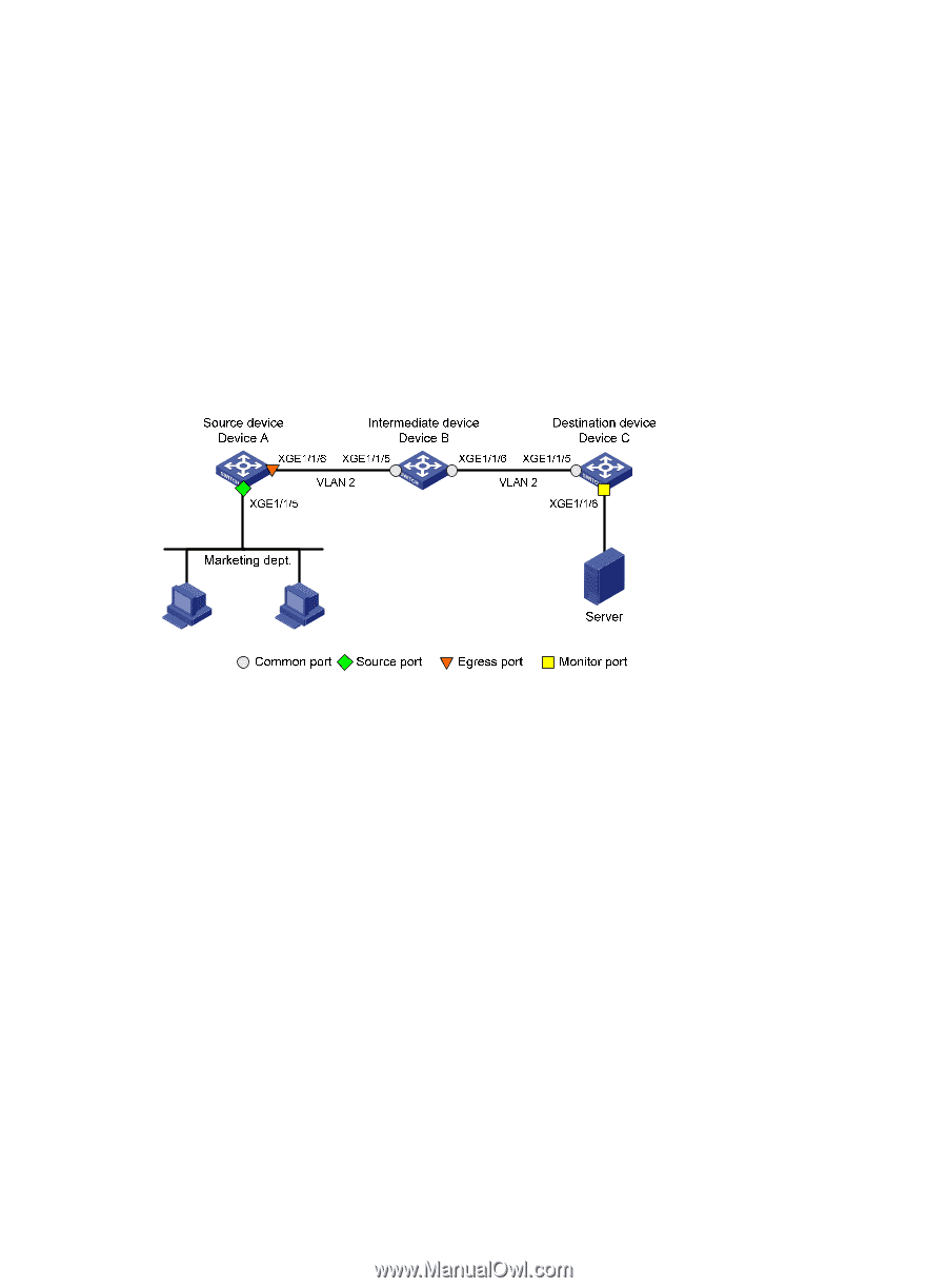
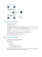
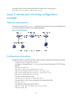
# Configure VLAN 10 as the remote probe VLAN of remote source mirroring group 1. [DeviceA] mirroring-group 1 remote-probe vlan 10 Layer 2 remote port mirroring configuration example Network requirements On the Layer 2 network shown in Figure 37, configure Layer 2 remote port mirroring to enable the server to monitor the bidirectional traffic of the marketing department. Figure 37 Network diagram Configuration procedure Configure the devices in the following order to make sure Layer 2 remote port mirroring work correctly. 1. Configure Device C (the destination device): # Configure Ten-GigabitEthernet 1/1/5 as a trunk port to permit the packets of VLAN 2 to pass through. system-view [DeviceC] interface ten-gigabitethernet 1/1/5 [DeviceC-Ten-GigabitEthernet1/1/5] port link-type trunk [DeviceC-Ten-GigabitEthernet1/1/5] port trunk permit vlan 2 [DeviceC-Ten-GigabitEthernet1/1/5] quit # Create a remote destination group. [DeviceC] mirroring-group 2 remote-destination # Create VLAN 2, which is to be configured as the remote probe VLAN. [DeviceC] vlan 2 # Disable MAC address learning for VLAN 2. [DeviceC-vlan2] undo mac-address mac-learning enable [DeviceC-vlan2] quit 117
-
 1
1 -
2
-
3
-
4
-
5
-
6
-
7
-
8
-
9
-
10
-
11
-
12
-
13
-
14
-
15
-
16
-
17
-
18
-
19
-
20
-
21
-
22
-
23
-
24
-
25
-
26
-
27
-
28
-
29
-
30
-
31
-
32
-
33
-
34
-
35
-
36
-
37
-
38
-
39
-
40
-
41
-
42
-
43
-
44
-
45
-
46
-
47
-
48
-
49
-
50
-
51
-
52
-
53
-
54
-
55
-
56
-
57
-
58
-
59
-
60
-
61
-
62
-
63
-
64
-
65
-
66
-
67
-
68
-
69
-
70
-
71
-
72
-
73
-
74
-
75
-
76
-
77
-
78
-
79
-
80
-
81
-
82
-
83
-
84
-
85
-
86
-
87
-
88
-
89
-
90
-
91
-
92
-
93
-
94
-
95
-
96
-
97
-
98
-
99
-
100
-
101
-
102
-
103
-
104
-
105
-
106
-
107
-
108
-
109
-
110
-
111
-
112
-
113
-
114
-
115
-
116
-
117
-
 118
118 -
 119
119 -
 120
120 -
 121
121 -
 122
122 -
 123
123 -
 124
124 -
 125
125 -
 126
126 -
 127
127 -
 128
128 -
129
-
130
-
131
-
132
-
133
-
134
-
135
-
136
-
137
-
138
-
139
-
140
-
141
-
142
-
143
-
144
-
145
-
146
-
147
-
148
 |
 |