HP 6125XLG R2306-HP 6125XLG Blade Switch Network Management and Monitoring Con - Page 99
NQA collaboration configuration example, Network requirements, Configuration procedure
 |
View all HP 6125XLG manuals
Add to My Manuals
Save this manual to your list of manuals |
Page 99 highlights
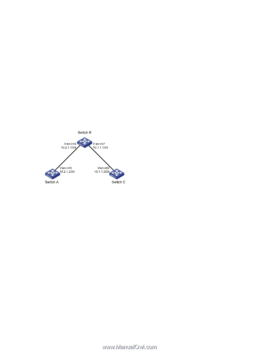
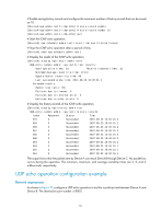
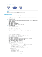
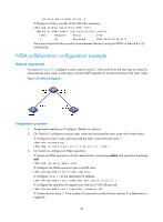
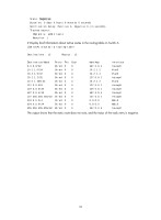
Failures due to other errors: 0 # Display the history records of the UDP echo operation. [DeviceA] display nqa history admin test1 NQA entry (admin admin, tag test1) history records: Index Response Status Time 1 25 Succeeded 2011-11-22 10:36:17.9 The output shows that the round-trip time between Device A and port 8000 on Device B is 25 milliseconds. NQA collaboration configuration example Network requirements As shown in Figure 30, configure a static route to Switch C with Switch B as the next hop on Switch A. Associate the static route, a track entry, and an ICMP operation to monitor the state of the static route. Figure 30 Network diagram Configuration procedure 1. Assign each interface an IP address. (Details not shown.) 2. On Switch A, configure a unicast static route and associate the static route with a track entry: # Configure a static route, and associate the static route with track entry 1. system-view [SwitchA] ip route-static 10.1.1.2 24 10.2.1.1 track 1 3. On Switch A, configure an NQA operation: # Create an NQA operation with the administrator name being admin and operation tag being test1. [SwitchA] nqa entry admin test1 # Configure the NQA operation type as ICMP echo. [SwitchA-nqa-admin-test1] type icmp-echo # Configure 10.2.1.1 as the destination IP address. [SwitchA-nqa-admin-test1-icmp-echo] destination ip 10.2.1.1 # Configure the operation to repeat at an interval of 100 milliseconds. [SwitchA-nqa-admin-test1-icmp-echo] frequency 100 # Create reaction entry 1. If the number of consecutive probe failures reaches 5, collaboration is triggered. 93
-
 1
1 -
2
-
3
-
4
-
5
-
6
-
7
-
8
-
9
-
10
-
11
-
12
-
13
-
14
-
15
-
16
-
17
-
18
-
19
-
20
-
21
-
22
-
23
-
24
-
25
-
26
-
27
-
28
-
29
-
30
-
31
-
32
-
33
-
34
-
35
-
36
-
37
-
38
-
39
-
40
-
41
-
42
-
43
-
44
-
45
-
46
-
47
-
48
-
49
-
50
-
51
-
52
-
53
-
54
-
55
-
56
-
57
-
58
-
59
-
60
-
61
-
62
-
63
-
64
-
65
-
66
-
67
-
68
-
69
-
70
-
71
-
72
-
73
-
74
-
75
-
76
-
77
-
78
-
79
-
80
-
81
-
82
-
83
-
84
-
85
-
86
-
87
-
88
-
89
-
90
-
91
-
92
-
93
-
 94
94 -
 95
95 -
 96
96 -
 97
97 -
 98
98 -
 99
99 -
 100
100 -
 101
101 -
 102
102 -
 103
103 -
 104
104 -
105
-
106
-
107
-
108
-
109
-
110
-
111
-
112
-
113
-
114
-
115
-
116
-
117
-
118
-
119
-
120
-
121
-
122
-
123
-
124
-
125
-
126
-
127
-
128
-
129
-
130
-
131
-
132
-
133
-
134
-
135
-
136
-
137
-
138
-
139
-
140
-
141
-
142
-
143
-
144
-
145
-
146
-
147
-
148
 |
 |