HP 6125XLG R2306-HP 6125XLG Blade Switch Network Management and Monitoring Con - Page 44
Display IPv4 NTP association information for Switch D
 |
View all HP 6125XLG manuals
Add to My Manuals
Save this manual to your list of manuals |
Page 44 highlights
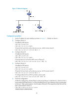
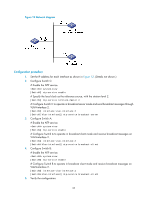
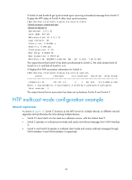
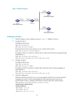
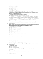
Leap indicator: 00 Clock jitter: 0.044281 s Stability: 0.000 pps Clock precision: 2^-10 Root delay: 0.00229 ms Root dispersion: 4.12572 ms Reference time: d0d289fe.ec43c720 Sat, Jan 8 2011 7:00:14.922 The output shows that Switch D has been synchronized to Switch C, the clock stratum level of Switch D is 3, and that of Switch C is 2. # Display IPv4 NTP association information for Switch D. [SwitchD-Vlan-interface2] display ntp-service sessions source reference stra reach poll now offset delay disper [1245]3.0.1.31 127.127.1.0 2 1 64 519 -0.0 0.0022 4.1257 Notes: 1 source(master),2 source(peer),3 selected,4 candidate,5 configured. Total sessions : 1 The output shows that an association has been set up between Switch D and Switch C. 5. Configure Switch B: Because Switch A and Switch C are on different subnets, you must enable the multicast functions on Switch B before Switch A can receive multicast messages from Switch C. # Enable IP multicast routing and IGMP. system-view [SwitchB] multicast routing-enable [SwitchB] interface vlan-interface 2 [SwitchB-Vlan-interface2] pim dm [SwitchB-Vlan-interface2] quit [SwitchB] vlan 3 [SwitchB-vlan3] port ten-gigabitethernet 1/1/5 [SwitchB-vlan3] quit [SwitchB] interface vlan-interface 3 [SwitchB-Vlan-interface3] igmp enable [SwitchB-Vlan-interface3] igmp static-group 224.0.1.1 [SwitchB-Vlan-interface3] quit [SwitchB] igmp-snooping [SwitchB-igmp-snooping] quit [SwitchB] interface ten-gigabitethernet 1/1/5 [SwitchB-Ten-GigabitEthernet1/1/5] igmp-snooping static-group 224.0.1.1 vlan 3 6. Configure Switch A: # Enable the NTP service. system-view [SwitchA] ntp-service enable # Configure Switch A to operate in multicast client mode and receive multicast messages on VLAN-interface 3. [SwitchA] interface vlan-interface 3 [SwitchA-Vlan-interface3] ntp-service multicast-client 7. Verify the configuration: 38
-
 1
1 -
2
-
3
-
4
-
5
-
6
-
7
-
8
-
9
-
10
-
11
-
12
-
13
-
14
-
15
-
16
-
17
-
18
-
19
-
20
-
21
-
22
-
23
-
24
-
25
-
26
-
27
-
28
-
29
-
30
-
31
-
32
-
33
-
34
-
35
-
36
-
37
-
38
-
 39
39 -
 40
40 -
 41
41 -
 42
42 -
 43
43 -
 44
44 -
 45
45 -
 46
46 -
 47
47 -
 48
48 -
 49
49 -
50
-
51
-
52
-
53
-
54
-
55
-
56
-
57
-
58
-
59
-
60
-
61
-
62
-
63
-
64
-
65
-
66
-
67
-
68
-
69
-
70
-
71
-
72
-
73
-
74
-
75
-
76
-
77
-
78
-
79
-
80
-
81
-
82
-
83
-
84
-
85
-
86
-
87
-
88
-
89
-
90
-
91
-
92
-
93
-
94
-
95
-
96
-
97
-
98
-
99
-
100
-
101
-
102
-
103
-
104
-
105
-
106
-
107
-
108
-
109
-
110
-
111
-
112
-
113
-
114
-
115
-
116
-
117
-
118
-
119
-
120
-
121
-
122
-
123
-
124
-
125
-
126
-
127
-
128
-
129
-
130
-
131
-
132
-
133
-
134
-
135
-
136
-
137
-
138
-
139
-
140
-
141
-
142
-
143
-
144
-
145
-
146
-
147
-
148
 |
 |