HP 6125XLG R2306-HP 6125XLG Blade Switch Network Management and Monitoring Con - Page 56
Displaying and maintaining SNTP, SNTP configuration example, Network requirements, Configuration
 |
View all HP 6125XLG manuals
Add to My Manuals
Save this manual to your list of manuals |
Page 56 highlights
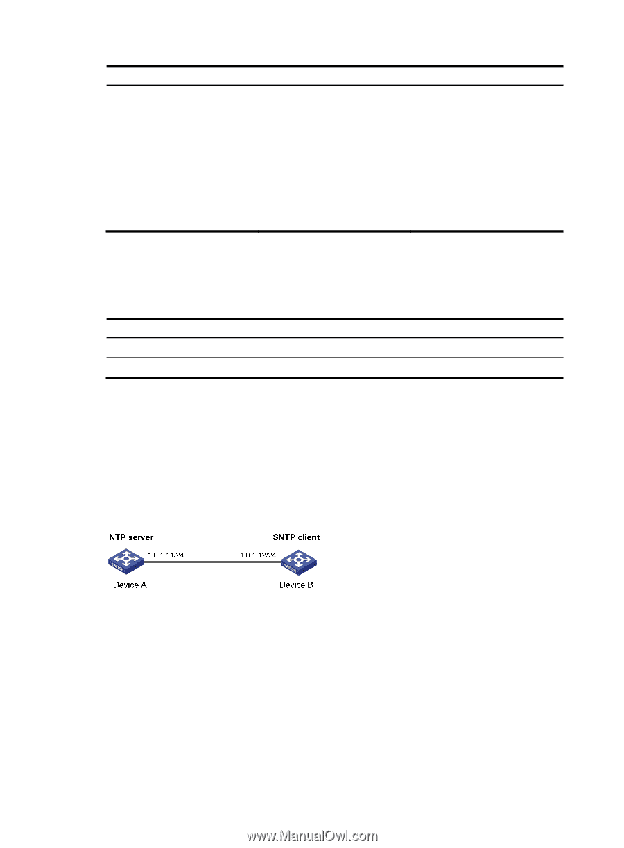
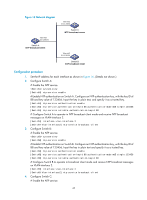
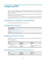
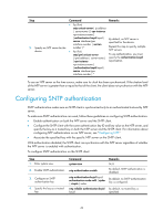
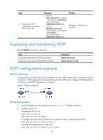
Step 5. Associate the SNTP authentication key with the specific NTP server. Command • For IPv4: sntp unicast-server { ip-address | server-name } [ vpn-instance vpn-instance-name ] authentication-keyid keyid • For IPv6: sntp ipv6 unicast-server { ipv6-address | server-name } [ vpn-instance vpn-instance-name ] authentication-keyid keyid Remarks By default, no NTP server is specified. Displaying and maintaining SNTP Execute display commands in any view. Task Display information about all SNTP associations. Display information about all IPv6 SNTP associations. Command display sntp sessions display sntp ipv6 sessions SNTP configuration example Network requirements Configure the local clock of Device A as a reference source, with the stratum level 2. Configure Device B to operate in SNTP client mode, and specify Device A as the NTP server. Configure NTP authentication on Device A and SNTP authentication on Device B. Figure 17 Network diagram Configuration procedure 1. Set the IP address for each interface as shown in Figure 17. (Details not shown.) 2. Configure Device A: # Enable the NTP service. system-view [DeviceA] ntp-service enable # Configure the local clock of Device A as a reference source, with the stratum level 2. [DeviceA] ntp-service refclock-master 2 # Enable NTP authentication on Device A. [DeviceA] ntp-service authentication enable 50
-
 1
1 -
2
-
3
-
4
-
5
-
6
-
7
-
8
-
9
-
10
-
11
-
12
-
13
-
14
-
15
-
16
-
17
-
18
-
19
-
20
-
21
-
22
-
23
-
24
-
25
-
26
-
27
-
28
-
29
-
30
-
31
-
32
-
33
-
34
-
35
-
36
-
37
-
38
-
39
-
40
-
41
-
42
-
43
-
44
-
45
-
46
-
47
-
48
-
49
-
50
-
 51
51 -
 52
52 -
 53
53 -
 54
54 -
 55
55 -
 56
56 -
 57
57 -
 58
58 -
 59
59 -
 60
60 -
 61
61 -
62
-
63
-
64
-
65
-
66
-
67
-
68
-
69
-
70
-
71
-
72
-
73
-
74
-
75
-
76
-
77
-
78
-
79
-
80
-
81
-
82
-
83
-
84
-
85
-
86
-
87
-
88
-
89
-
90
-
91
-
92
-
93
-
94
-
95
-
96
-
97
-
98
-
99
-
100
-
101
-
102
-
103
-
104
-
105
-
106
-
107
-
108
-
109
-
110
-
111
-
112
-
113
-
114
-
115
-
116
-
117
-
118
-
119
-
120
-
121
-
122
-
123
-
124
-
125
-
126
-
127
-
128
-
129
-
130
-
131
-
132
-
133
-
134
-
135
-
136
-
137
-
138
-
139
-
140
-
141
-
142
-
143
-
144
-
145
-
146
-
147
-
148
 |
 |