HP 6125XLG R2306-HP 6125XLG Blade Switch Network Management and Monitoring Con - Page 9
Tracert
 |
View all HP 6125XLG manuals
Add to My Manuals
Save this manual to your list of manuals |
Page 9 highlights
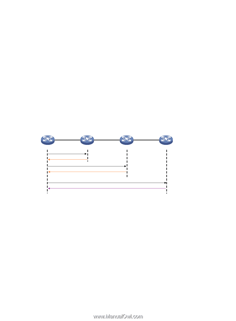
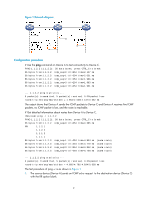
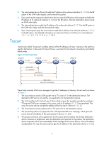
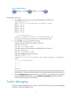
2. The intermediate device (Device B) adds the IP address of its outbound interface (1.1.2.1) to the RR option of the ICMP echo request, and forwards the packet. 3. Upon receiving the request, the destination device copies the RR option in the request and adds the IP address of its outbound interface (1.1.2.2) to the RR option. Then the destination device sends an ICMP echo reply. 4. The intermediate device adds the IP address of its outbound interface (1.1.1.2) to the RR option in the ICMP echo reply, and then forwards the reply. 5. Upon receiving the reply, the source device adds the IP address of its inbound interface (1.1.1.1) to the RR option. The detailed information of routes from Device A to Device C is formatted as: 1.1.1.1 {1.1.1.2; 1.1.2.1} 1.1.2.2. Tracert Tracert (also called "Traceroute") enables retrieval of the IP addresses of Layer 3 devices in the path to a specific destination. In the event of network failure, use tracert to test network connectivity and identify failed nodes. Figure 2 Tracert operation Device A 1.1.1.1/24 Device B 1.1.2.1/24 Device C 1.1.3.1/24 Device D 1.1.1.2/24 1.1.2.2/24 1.1.3.2/24 Hop Lmit=1 TTL exceeded Hop Lmit=2 TTL exceeded Hop Lmit=n UDP port unreachable Tracert uses received ICMP error messages to get the IP addresses of devices. Tracert works as shown in Figure 2: 1. The source device sends a UDP packet with a TTL value of 1 to the destination device. The destination UDP port is not used by any application on the destination device. 2. The first hop (Device B, the first Layer 3 device that receives the packet) responds by sending a TTL-expired ICMP error message to the source, with its IP address (1.1.1.2) encapsulated. This way, the source device can get the address of the first Layer 3 device (1.1.1.2). 3. The source device sends a packet with a TTL value of 2 to the destination device. 4. The second hop (Device C) responds with a TTL-expired ICMP error message, which gives the source device the address of the second Layer 3 device (1.1.2.2). 5. This process continues until a packet sent by the source device reaches the ultimate destination device. Because no application uses the destination port specified in the packet, the destination device responds with a port-unreachable ICMP message to the source device, with its IP address encapsulated. This way, the source device gets the IP address of the destination device (1.1.3.2). 3
-
 1
1 -
2
-
3
-
 4
4 -
 5
5 -
 6
6 -
 7
7 -
 8
8 -
 9
9 -
 10
10 -
 11
11 -
 12
12 -
 13
13 -
 14
14 -
15
-
16
-
17
-
18
-
19
-
20
-
21
-
22
-
23
-
24
-
25
-
26
-
27
-
28
-
29
-
30
-
31
-
32
-
33
-
34
-
35
-
36
-
37
-
38
-
39
-
40
-
41
-
42
-
43
-
44
-
45
-
46
-
47
-
48
-
49
-
50
-
51
-
52
-
53
-
54
-
55
-
56
-
57
-
58
-
59
-
60
-
61
-
62
-
63
-
64
-
65
-
66
-
67
-
68
-
69
-
70
-
71
-
72
-
73
-
74
-
75
-
76
-
77
-
78
-
79
-
80
-
81
-
82
-
83
-
84
-
85
-
86
-
87
-
88
-
89
-
90
-
91
-
92
-
93
-
94
-
95
-
96
-
97
-
98
-
99
-
100
-
101
-
102
-
103
-
104
-
105
-
106
-
107
-
108
-
109
-
110
-
111
-
112
-
113
-
114
-
115
-
116
-
117
-
118
-
119
-
120
-
121
-
122
-
123
-
124
-
125
-
126
-
127
-
128
-
129
-
130
-
131
-
132
-
133
-
134
-
135
-
136
-
137
-
138
-
139
-
140
-
141
-
142
-
143
-
144
-
145
-
146
-
147
-
148
 |
 |