HP Workstation xw3100 HP Workstation xw3100 - Service and Technical Reference - Page 140
Drive Installation Guidelines, Device Classes, Single-Drive Cable, Two-Drive Cable
 |
View all HP Workstation xw3100 manuals
Add to My Manuals
Save this manual to your list of manuals |
Page 140 highlights
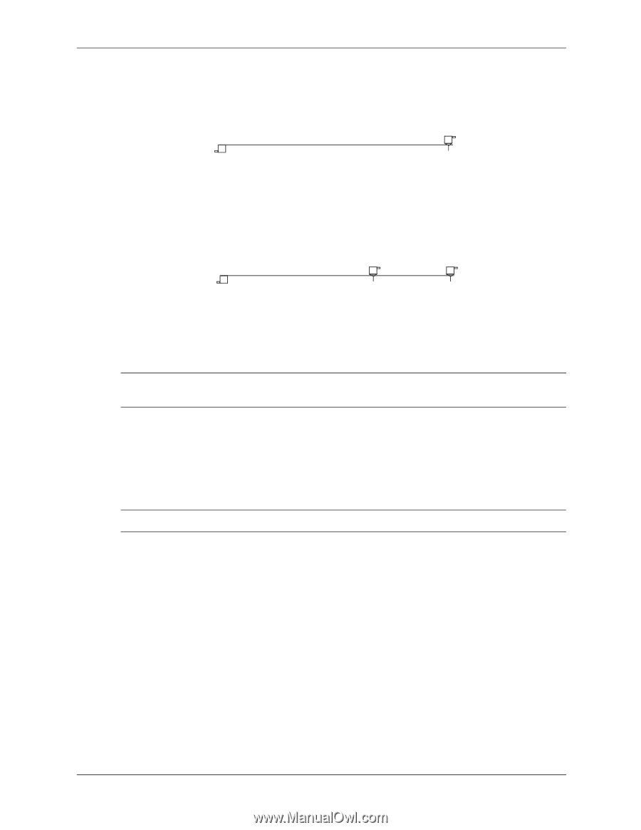
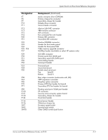
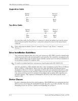
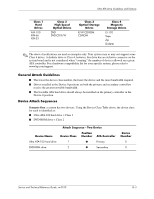
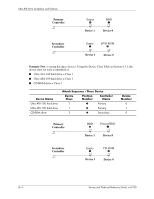
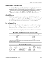
Ultra ATA Drive Guidelines and Features Single-Drive Cable System Board Device 0 (master) Blue Face Two-Drive Cable System Board Black Face Device 1 (slave) Device 0 (master) Blue Gray Black Face Face Face On a two-drive cable, the Drive/Device 0 connector is always the farthest one from the system board connector and the Drive/Device 1 connector is always the closest to the system board connector. ✎ Some cables may be labeled "Drive 0" instead of "Device 0" and "Drive 1" instead of "Device 1". Drive Installation Guidelines Your workstation supports three drive bays and contains two ATA (IDE) controller channels with a dedicated connector on the system board for each controller. One controller is designated as the primary and the other as the secondary. Each controller can have up to two devices attached to it via an industry-standard 80-conductor cable. ✎ To install a secondary hard drive, you must use a dual-headed cable (PN 108950-051). Any drive attached to a ATA controller must have a drive designation, such as Device O (Master Drive) or Device 1 (Slave Drive). Drives set to the cable select mode will automatically be designated as Device 0 or Device 1 depending on where they are connected on the device cable and whether or not they are the only drive connected to the cable. For optimal performance of your system, all drives need to be attached to the primary and secondary ATA controllers in a specified sequence. This sequence is determined by the device class and by specific attach sequence rules. Device Classes In order to determine the best drive attach sequence, ATA/ATAPI drives are segregated into four different classes based upon the bandwidth demands they place on an ATA controller. The most demanding devices are in Class 1 and the least demanding are in Class 4. G-2 Service and Technical Reference Guide, xw3100
-
 1
1 -
2
-
3
-
4
-
5
-
6
-
7
-
8
-
9
-
10
-
11
-
12
-
13
-
14
-
15
-
16
-
17
-
18
-
19
-
20
-
21
-
22
-
23
-
24
-
25
-
26
-
27
-
28
-
29
-
30
-
31
-
32
-
33
-
34
-
35
-
36
-
37
-
38
-
39
-
40
-
41
-
42
-
43
-
44
-
45
-
46
-
47
-
48
-
49
-
50
-
51
-
52
-
53
-
54
-
55
-
56
-
57
-
58
-
59
-
60
-
61
-
62
-
63
-
64
-
65
-
66
-
67
-
68
-
69
-
70
-
71
-
72
-
73
-
74
-
75
-
76
-
77
-
78
-
79
-
80
-
81
-
82
-
83
-
84
-
85
-
86
-
87
-
88
-
89
-
90
-
91
-
92
-
93
-
94
-
95
-
96
-
97
-
98
-
99
-
100
-
101
-
102
-
103
-
104
-
105
-
106
-
107
-
108
-
109
-
110
-
111
-
112
-
113
-
114
-
115
-
116
-
117
-
118
-
119
-
120
-
121
-
122
-
123
-
124
-
125
-
126
-
127
-
128
-
129
-
130
-
131
-
132
-
133
-
134
-
 135
135 -
 136
136 -
 137
137 -
 138
138 -
 139
139 -
 140
140 -
 141
141 -
 142
142 -
 143
143 -
 144
144 -
 145
145 -
146
-
147
-
148
 |
 |